19.4 Working with HDR (High Dynamic Range Control) 163
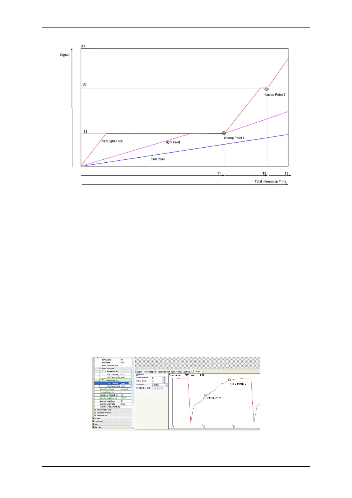
Figure 2: Integration time of different bright pixels
In the diagram you can see the signal line of three different bright pixels. The slope depends of the light intensity ,
thus it is per pixel the same here (granted that the light intensity is temporally constant). Given that the very light
pixel is limited soon at the signal levels S1 and S2, the whole integration time is lower compared to the dark pixel. In
practice, the parts of the integration time are very different. T1, for example, is 95% of T
total
, T2 only 4% and T3 only
1%. Thus, a high decrease of the very light pixels can be achieved. However, if you want to divide the integration
thresholds into three parts that is S2 = 2 x S1 and S3 = 3 x S1, a hundredfold brightness of one pixel's step from S2
to S3, compared to the step from 0 and S1 is needed.
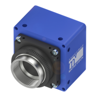
19.4.1.3 Using HDR with mvBlueFOX-x00w
Figure 3 is showing the usage of the HDR mode. Here, an image sequence was created with the integration time
between 10us and 100ms. You can see three slopes of the HDR mode. The "waves" result from the rounding during
the three exposure phases. They can only be partly adjusted during one line period of the sensor.
Figure 3: wxPropView HDR screenshot
MATRIX VISION GmbH