19.9 Working with the Hardware Real-Time Controller (HRTC) 185
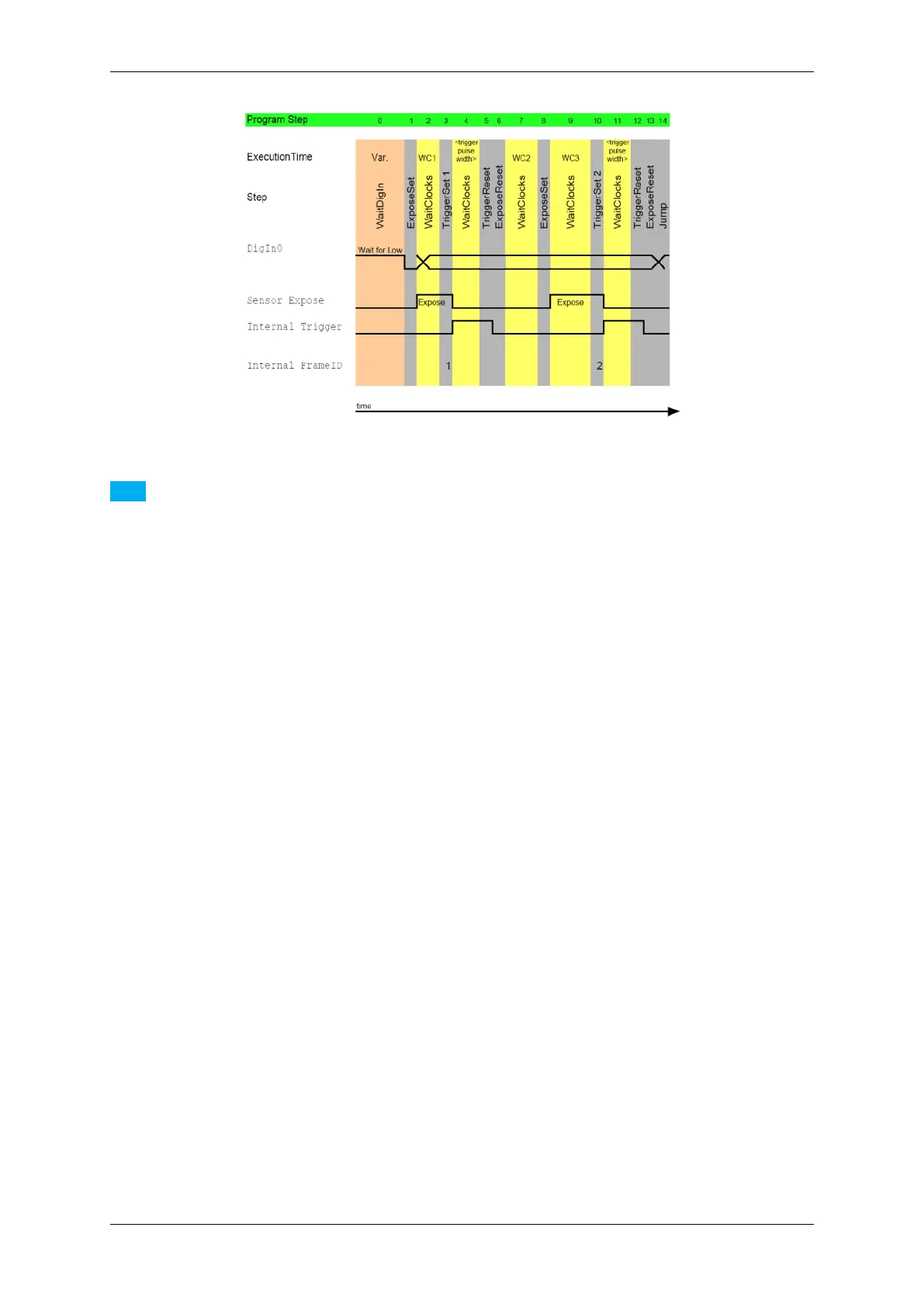
Figure 1: Take two images with different expose times after an external trigger
Note
Due to the internal loop to wait for a trigger signal, the WaitClocks call between "TriggerSet 1" and "Trigger←-
Reset" constitute 100. For this reason, the trigger signal cannot be missed.
Before the ExposeReset, you have to call the TriggerReset otherwise the normal flow will continue and the
image data will be lost!
The sensor expose time after the TriggerSet is 0.
See also
Download this sample as an rtp file: 2Images2DifferentExposureTimes.rtp with two consecu-
tive exposure times (10ms / 20ms). To open the file in wxPropView (p. 77), click on "Digital I/O ->
HardwareRealTimeController -> Filename" and select the downloaded file. Afterwards, click
on "int Load( )" to load the HRTC program. There are timeouts added in line 4 and line 14 to illustrate the
different exposure times.
Using a CMOS model (e.g. the mvBlueFOX-MLC205), a sample with four consecutive exposure times (10ms /
20ms / 40ms / 80ms) triggered just by one hardware input signal would look like this:
0. WaitDigin DigIn0->On
1. TriggerSet
2. WaitClocks 10000 (= 10 ms)
3. TriggerReset
4. WaitClocks 1000000 (= 1 s)
5. TriggerSet
6. WaitClocks 20000 (= 20 ms)
7. TriggerReset
8. WaitClocks 1000000 (= 1 s)
9. TriggerSet
10. WaitClocks 40000 (= 40 ms)
11. TriggerReset
12. WaitClocks 1000000 (= 1 s)
13. TriggerSet
14. WaitClocks 80000 (= 40 ms)
15. TriggerReset
16. WaitClocks 1000000 (= 1 s)
17. Jump 0
See also
This second sample is also available as an rtp file: MLC205_four_images_diff_exp.rtp.
MATRIX VISION GmbH