8.4 Single-board version (mvBlueFOX-MLC2xx) 63
10 OUT0+ Opto-
isolated
digital
output 0
(Positive
voltage)
OUT0 TTL com-
pliant dig-
ital output
0
IN2 LVTTL
compliant
digital
input 2
violet violet
11 IN0- Opto-
isolated
digital
input 0
(Negative
voltage)
IN1 TTL com-
pliant digi-
tal input 1
IN1 LVTTL
compliant
digital
input 1
gray gray
12 IN0+ Opto-
isolated
digital
input 0
(Positive
voltage)
IN0 TTL com-
pliant digi-
tal input 0
IN0 LVTTL
compliant
digital
input 0
pink pink
Note
I2C bus uses 3.3 Volts. Signals have a 2kOhm pull-up resistor. Access to the I2C bus from an application is
possible for mvBlueFOX-MLC devices using an mvBlueFOX driver with version 1.12.44 or newer.
Manufacturer (suitable board-to-wire connector): Molex
Part number: 0510211200 1.25mm Housing
Link: http://www.molex.com/molex/products/datasheet.jsp?part=active/0510211200←-
_CRIMP_HOUSINGS.xml&channel=Products&Lang=en-US
Manufacturer (multi-pin connector for board-to-board connection): e.g. Garry
Link: http://www.mpe-connector.de/index.php?lang=de&menu=16&mating=1841&id_←-
product=6591 (recommended variant: 659-1-012-O-F-RS0-xxxx; xxxx = length of the pins)
See also
Suitable assembled cable accessories for mvBlueFOX-MLC: What's inside and accessories (p. 22)
High-Speed USB design guidelines (p. 14)
More information about the usage of retrofittable ferrite (p. 17)
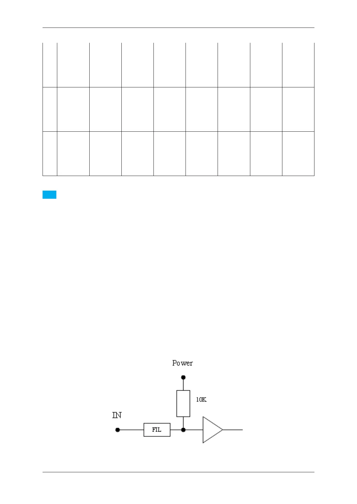
8.4.2.3.1 Electrical characteristic
Digital inputs TTL
Figure 23: TTL digital inputs block diagram
MATRIX VISION GmbH