8.4 Single-board version (mvBlueFOX-MLC2xx) 65
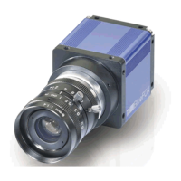
Figure 25: Opto-isolated digital inputs block diagram with example circuit
Delay
Characteristics Symbol Typ. Unit
Turn-On time t
ON
3 us
The inputs can be connected directly to +3.3 V and 5 V systems. If a higher voltage is used, an external resistor
must be placed in series (Figure 25).
Used input voltage External series resistor
3.3V .. 5V none
12V 680 Ohm
24V 2 KOhm
Comment Min Typ Max Unit
U
IN
V
IH
3 5.5 V
V
IL
-
5.←-
5
0.8 V
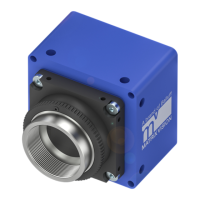
Opto-isolated digital outputs
Figure 26: Opto-isolated digital outputs block diagram with example circuit
Delay
MATRIX VISION GmbH