M
AVTMTTR310 Rev 8 May 2016
16
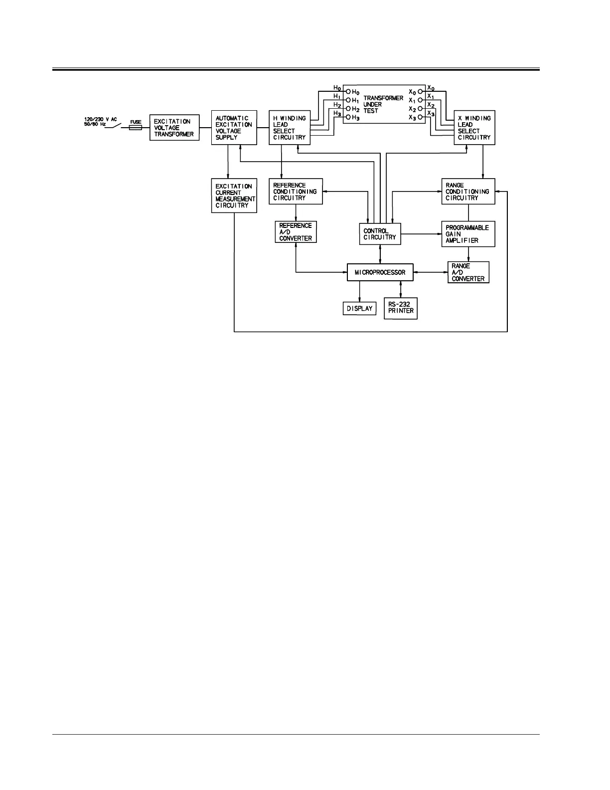
Figure 4-1. Three-Phase TTR310 Test Set Block Diagram
The range and reference conditioning circuitries isolate a transformer under test
from the TTR310 measurement circuitry and provide conditioning of the input
and output measurement signals. The programmable gain amplifier is used for
additional conditioning of the transformer output signals.
Both the reference A/D converter and the range A/D converter are used to
convert the analog measurement signals to their digital replica. The converted
output digital signals are applied to the microprocessor.
The microprocessor orchestrates all steps of the TTR310 test set operation. It
provides proper sequence of operation, gathers and calculates the test results,
provides interfacing with the display, RS232/printer port, and the control
circuitry. The control circuitry interfaces with virtually all function blocks
described, providing proper control sequence of the TTR310 test set operation.