M
AVTMTTR310 Rev 8 May 2016
20
4. Connect the heavy-duty clips marked X1 and X2 of the test lead to the
corresponding (low-voltage winding) terminals of the transformer under test.
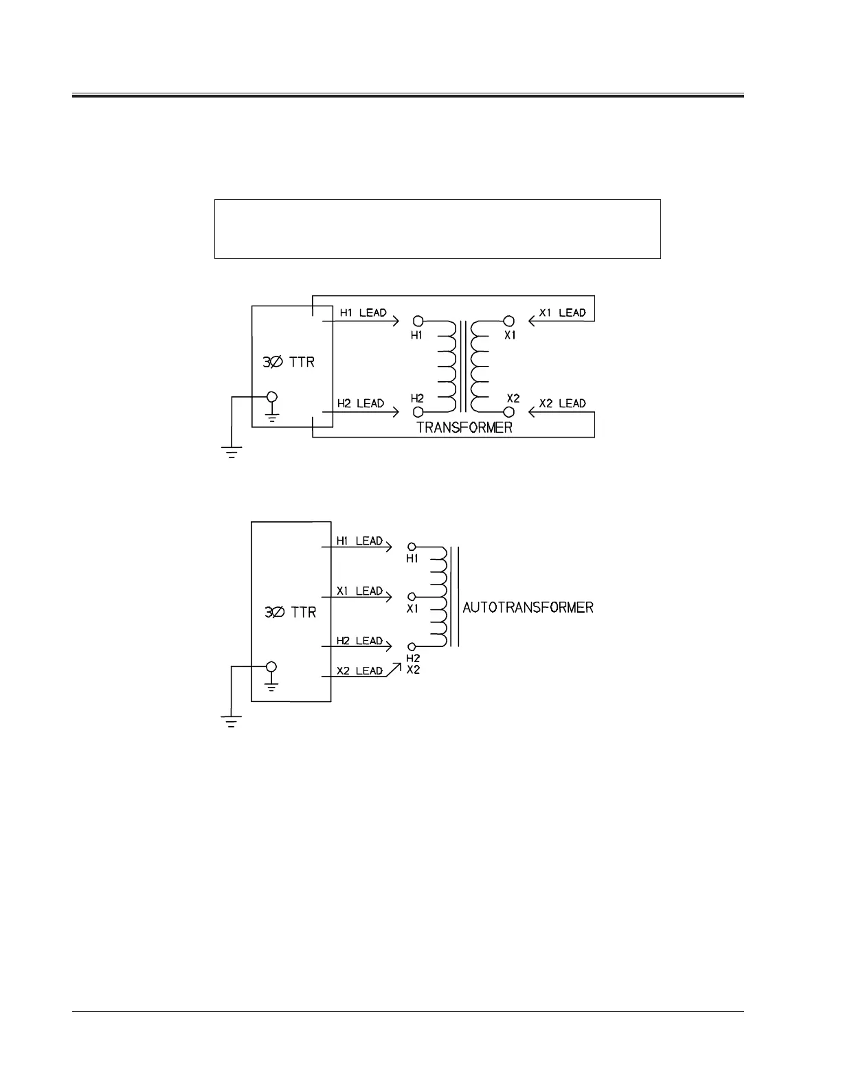
Figures 5-1 and 5-2 show test setups for single-phase transformers. Figures
5-3 and 5-4 show test setups for regulators.
NOTE: When using a three-phase cable set, connect heavy-duty clips marked
H1, H2 and X1, X2 to the corresponding terminals of the transformer under
test. The unused clips should be kept clear of ground and personnel.
Figure 5-1. Setup for Testing Single-Phase Transformer
Figure 5-2. Setup for Testing Single-Phase Autotransformer
To test windings other than H1 – H2 and X1 – X2, ensure that the heavy-duty
clip marked H1 is connected to the lower numbered terminal and H2 to the
higher numbered terminal of the high-voltage winding. Similarly, X1 and X2
should be connected to the low-voltage winding. Test lead markings for the
ANSI, CEI/IEC, and Australian standards are as shown in Table 5-1.