SETUP AND CONNECTIONS
AVTMTTR310 Rev 8 May 2016
31
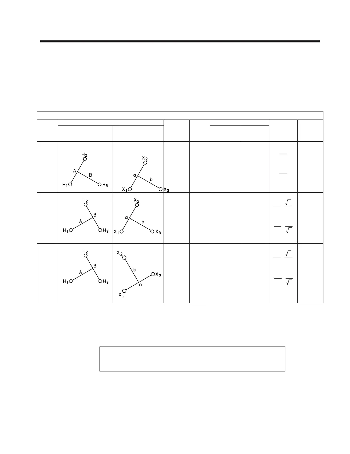
T-Type Transformers
T-type transformers represent the special type of thee-phase transformers. This
transformer may be tested as a single phase transformer. In this case, the jumpers
indicated in Table 5-3 should be applied to the appropriate terminals of the T-
type transformers. The TTR310 measured turn ratio should be compared to the
calculated turn ratio indicated in Table 5-3.
Table 5-3. T-type Transformer Winding Phase Relationship
Winding Connection Winding Tested
IEC
Vector
Group
High-Voltage
Winding (H)
Low-Voltage
Winding (X)
External
jumpers
Phase
tested
High-
Voltage
Winding
Low-
Voltage
Winding
Calculated
Turn Ratio
Remarks
T-T
0
-
H
1
-H
2
X
1
-X
2
A
B
H
1
- H
2
H
1
– H
3
X
1
- X
2
X
1
– X
3
V
V
H
X
V
V
H
X
T-T
30
lag
H
2
-H
3
X
1
-X
2
A
B
H
1
– H
3
H
2
– H
3
X
1
- X
2
X
1
– X
3
V
V
H
X
v
3
2
T-T
30
lead
H
2
-H
3
X
1
–X
3
A
B
H
1
– H
3
H
2
– H
3
X
1
– X
3
X
2
– X
1
2
3
V
V
X
H
v
NOTE: When testing T-type transformer, the diagram number 1 should be
entered at the Quick Test Setup screen (See Figure 6-3) or at the Full Test
Setup 1 screen (See Figure 6-6).
3
2
V
V
X
H
3
2
V
V
X
H