DESCRIPTION
AVTMTTR310 Rev 8 May 2016
17
Controls, Indicators, and Connectors
TEST VOLTAGE
ON
Red indicator lamp indicates when lit that test voltage is being
supplied to a transformer.
EMERGENCY
TEST OFF
This red push button interrupts testing. When pressed, the
switch is locked in off position. To reset the switch, twist the
button in the direction indicated by the arrows.
DISPLAY
SCREEN
Color LCD shows menus and test information.
KEYPAD 16-button keypad for entering menu selections and navigating
through the various screens. In addition to numbered keys
1 through 9, plus 0, there is a CLR (clear) button, R (raise or
right) button, L (lower or left) button, an ENT (enter) button,
a decimal point button, and an * (asterisk) button. An audible
tone confirms that you have successfully pressed a button.
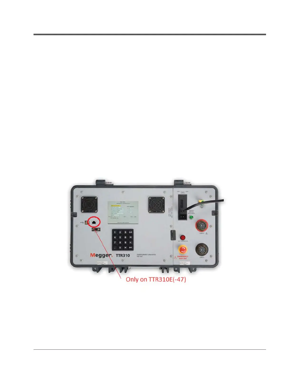
Figure 4-2. Three-Phase TTR310 Control Panel
GROUND Wing-nut terminal allows connection of test set to earth
ground.
CABLE H Plug receptacle for connecting test leads to the high-voltage
(H) winding of a transformer