SETUP AND CONNECTIONS
AVTMTTR310 Rev 8 May 2016
23
The unused H0 and X0 terminals should be kept clear of ground and personnel
because they could become energized during the test. Refer to Table 5-2 for test
lead markings.
With delta connected windings, H0 or X0 is not used. With wye connected
windings, a neutral connection is normally available.
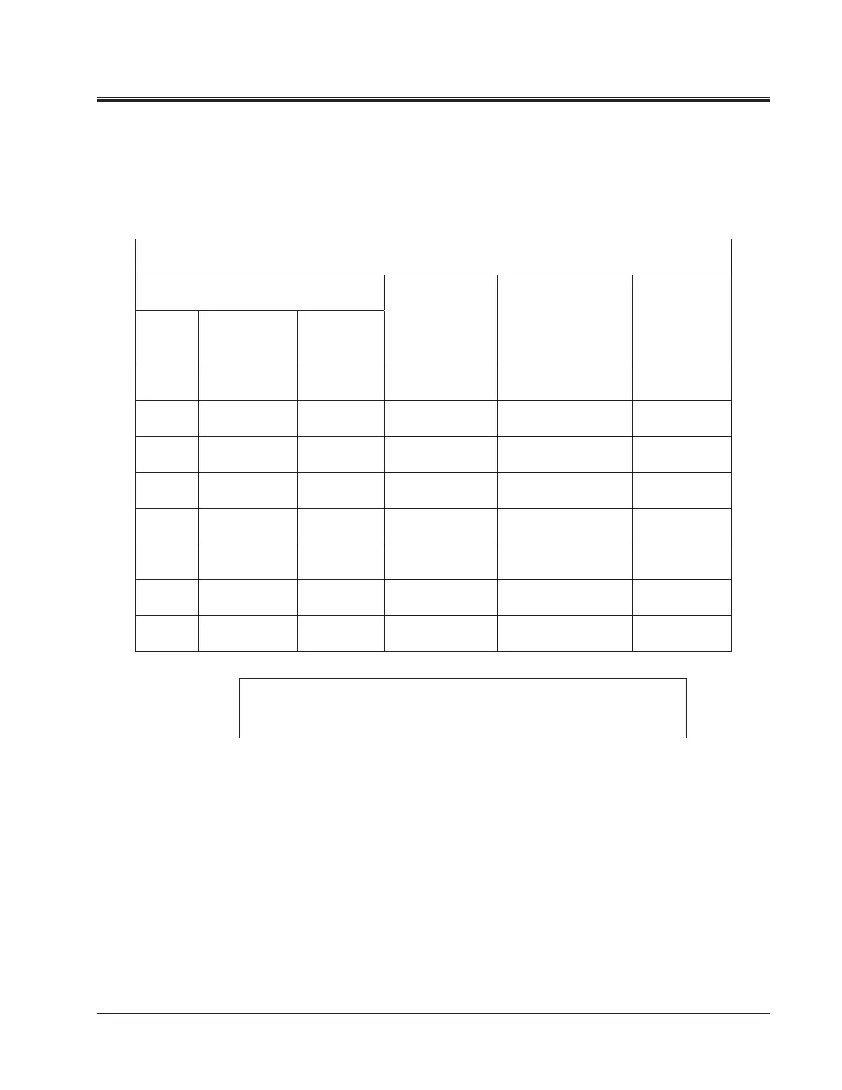
Table 5-2. Test Lead Markings for Three-Phase Transformers
Test Lead Marking Transformer Heavy-Duty Clip Test Lead
ANSI CEI/IEC Australian Terminal
Voltage
Boot Color Color Band
H0 1N N Neutral Red White
H1 1U A
2
/A
4
High Red Red
H2 1V B
2
/B
4
High Red Yellow
H3 1W C
2
/C
4
High Red Blue
X0 2N N Neutral Black White
X1 2U a
1
/a
2
/a
4
Low Black Red
X2 2V b
1
/b
2
/b
4
Low Black Yellow
X3 2W c
1
/c
2
/c
4
Low Black Blue
Note: According to Australian standard, wye and delta transformer winding
connections have a numerical suffix of 1 and 2. The zigzag transformers have a
numerical suffix of 4. See Table 5-6.