QUICK START MANUAL Document reference MAVM600MK2MPS-QS/E
VM600
Mk2
machinery protection system (MPS) Edition 2 - February 2021
2-26
RLC16
Mk2
relay module
OVERVIEW OF VM600
Mk2
MACHINERY PROTECTION SYSTEM (MPS) HARDWARE
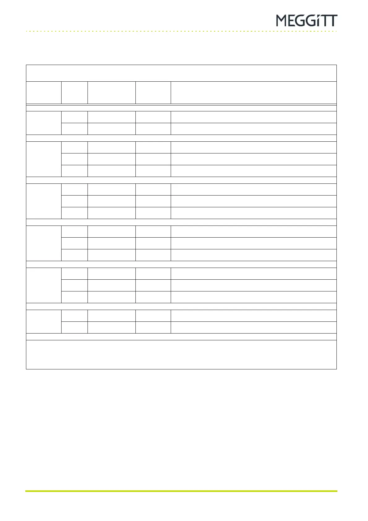
Table 2-8: RLC16
Mk2
module J2 connector pinouts
RLC16
Mk2
J2 connector: RELAYS
Label Pin
Name /
function
Direction Definition
6
1 RLY6_NO O Relay 6 normally open (NO) contact
2 RLY6_COM O Relay 6 common (COM) contact
7
3 RLY7_NC O Relay 7 normally closed (NC) contact
4 RLY7_NO O Relay 7 normally open (NO) contact
5 RLY7_COM O Relay 7 common (COM) contact
8
6 RLY8_NC O Relay 8 normally closed (NC) contact
7 RLY8_NO O Relay 8 normally open (NO) contact
8 RLY8_COM O Relay 8 common (COM) contact
9
9 RLY9_NC O Relay 9 normally closed (NC) contact
10 RLY9_NO O Relay 9 normally open (NO) contact
11 RLY9_COM O Relay common (COM) contact
10
12 RLY10_NC O Relay 10 normally closed (NC) contact
13 RLY10_NO O Relay 10 normally open (NO) contact
14 RLY10_COM O Relay 10 common (COM) contact
11
15 RLY11_NC O Relay 11 normally closed (NC) contact
16 RLY11_NO O Relay 11 normally open (NO) contact
Notes
COM = common, DSI = discrete signal interface, G = ground, HI = high, I = input, LO = low, NC = normally closed, NO = normally open,
O = output, PG = protective ground, R = return, S = shield, SHIELD = shield / protective ground,
SPS = sensor/measurement chain power supply
 Loading...
