124
Monitoring the percentage of the drive torque current relative to the motor rated current.
Monitoring the percentage of the flux current relative to the motor rated current.
Monitoring the percentage of the output torque of the drive relative to the motor rated torque.
Monitoring the percentage of the output power of the drive relative to the motor rated power.
Estimating the rotor frequency of the motor under the open loop vector condition.
The rotor frequency of the motor measured based on the encoder under the closed loop vector condition.
Monitoring the output power of the drive.
Monitoring the DC bus voltage of drive.
UnitTens
Thousands
BIT0 : RUN/STOP
BIT1 : REV/FWD
BIT2 : Running at zero speed
BIT3 : Accelerating
Hundreds
BIT0 : Decelerating
BIT1 : Running at constant speed
BIT2 : Pre-exciting
BIT3 : Tuning
BIT0 : Over-current limiting
BIT1 : DC over-voltage limiting
BIT2 : Torque limiting
BIT3 : Speed limiting
BIT0 : Drive in fault
BIT1 : Speed control
BIT2 : Torque control
BIT3 : Position control
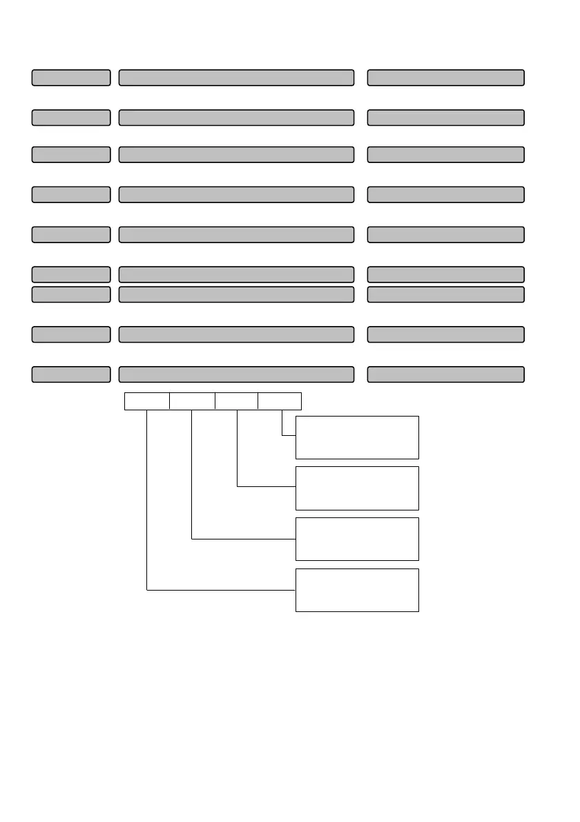
Fig. 6-2 Operation state of drive
Unit place of LED:
BIT0: RUN/STOP
When the drive is in stop state, the value for the BIT0 place is 0, otherwise, it is 1.
BIT1: REV/FWD
When the drive runs forward, the value for the BIT1 place is 0, otherwise, it is 1.
The corresponding bit will be set to 1 when the condition is met for other bits.
Output torque -300.0~300.0%(0.0%)P01.10
Operation state of drive 0~FFFFH (0)P01.17
DC bus voltage 0~800V (0)P01.16
Low level of output (
Wh) 0~9999kwh (0)P01.15
High level of output (
Wh)
0~65535*10000kwh (0)P01.14
Measured frequency of moto
-600.00~600.00 (0.00)P01.13
Estimated frequency of moto
-600.00~600.00(0.00)P01.12
Motor powe
0~200.0%(0.0%)P01.11
Flux current
0~100.0%(0.0%)P01.09
 Loading...