125
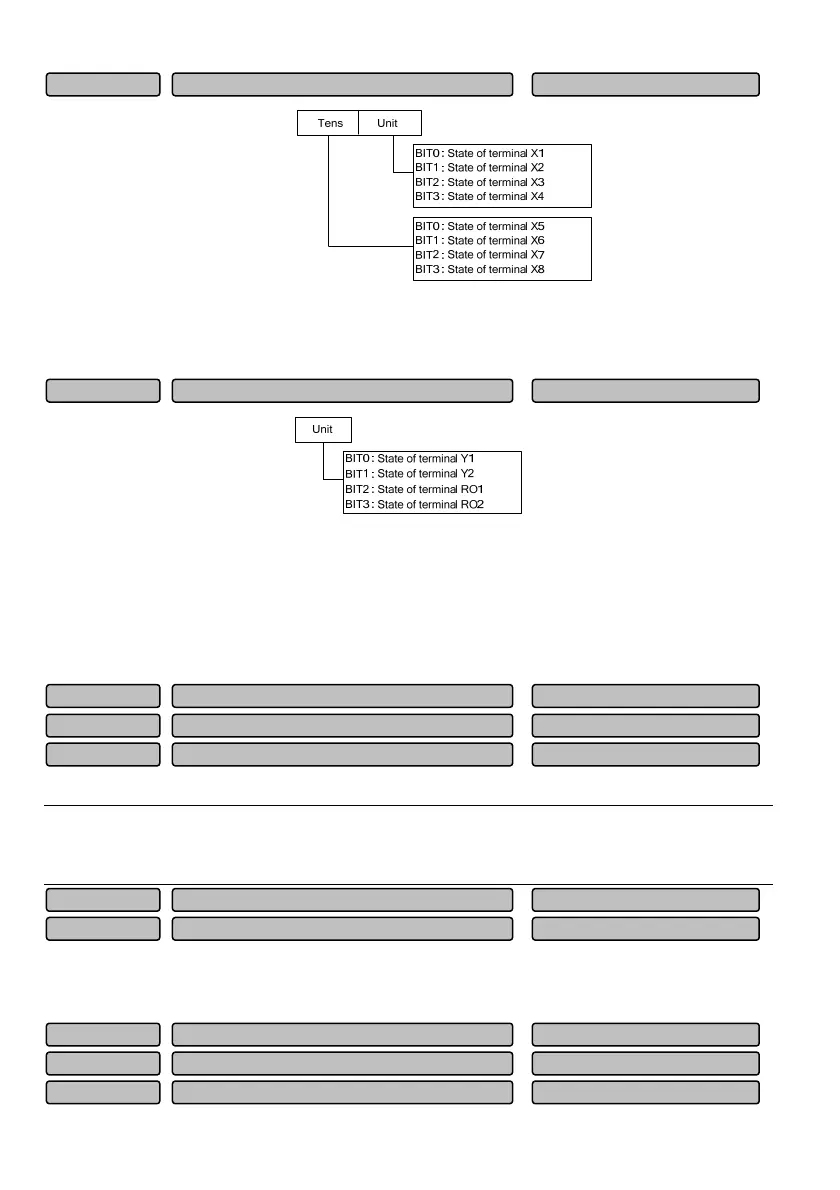
Fig. 6-3 State of digital input terminal
Displaying the ON/OFF state of 8 terminals (X1~X8). “0” means that the terminal is in “OFF” state and “1”
means that the terminal is in “ON” state.
Fig. 6-4 State of digital output terminal
The function code P01.19 can display the state of the output terminals (Y1 and Y2) and the relays (RO1
and RO2). When the signal is output, the corresponding place of P01.19 will be set as 1. For example, if
the signals are output from the terminal Y1 only, the place of BIT0 will be set as 1, therefore, the value
displayed by P01.19 is 1. The value displayed by P01.19 will be 8 when the signal is output from the relay
RO2 only.
P01.20~P01.22 are used to display the analog input signal before the adjustment.
Note
When the current input is selected for the analog input, the AI input range is 4 to 20mA, and the corresponding
display range is 2 to 10.
P01.23 and P01.24 are used to display the percentage of the analog output relative to the full range. For
example, the function of AO1 is set as “output frequency”. If the maximum frequency is 100Hz and actual
running frequency is 50Hz, P01.23 will displays 50%.
Process closed loop erro
-100.0~100.0%(0.0%)
P01.27
Process closed loop feedbac
-100.0~100.0%(0.0%)
P01.26
Process closed loop reference
-100.0~100.0%(0.0%)
P01.25
AO2 output 0.0~100.0%(0.0%)P01.24
AO1 output
0.0~100.0%(0.0%)
P01.23
AI3 input voltage
-10.00~10.00V(0.00V)
P01.22
AI2 input voltage
-10.00~10.00V(0.00V)
P01.21
AI1 input voltage -10.00~10.00V(0.00V)P01.20
State of digital output terminal 0~FH (0)P01.19
State of digital input terminal 0~FFH (00)P01.18
 Loading...