197
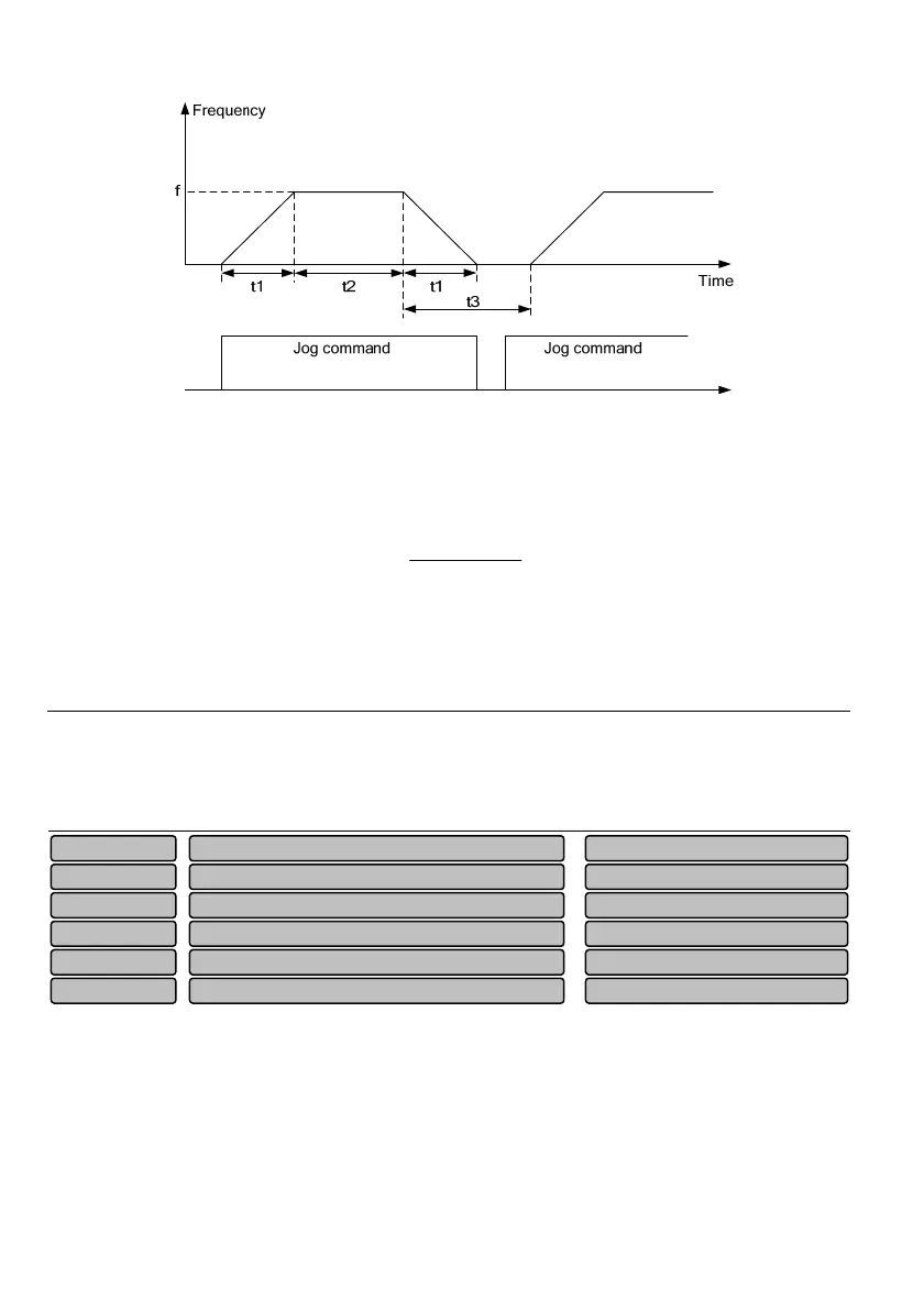
Fig. 6-61 Description of the jog running parameter
As shown in Fig. 6-61, t1 is the jog acceleration and deceleration time (P11.16) of actual running. t2 is the
jog time and t3 is the jog interval time (P11.17). f is the jog running frequency (P11.18).
The jog acceleration and deceleration time t
1
of actual running is determined by the following equation:
15.02
18.1116.11
1
t
P
PP ×
=
The jog interval time (P11.17) is the waiting time interval from canceling the jog command last time to the
next valid jog command. In the interval, the jog command will not make the drive operate. The drive
operates at zero frequency of the non-output. If the jog command persists, the jog command will be
executed after the interval. The jog command is executed immediately after the jog interval.
Note
1. The jog running starts and stops according to start mode 0 and stop mode 0. The unit for the acceleration
and deceleration time is second by default.
2. The operation panel, control terminal and serial port can perform the jog control.
P11.19~P11.24 are designed to let the output frequency of the drive avoid the resonance frequency point
of the mechanical load.
The set frequency of the drive can skip around some frequency point in accordance with the mode shown
in Fig.6-62, up to 3 skip ranges can be defined.
Lower limit of ski
fre
uenc
3 0.00~P11.23 Hz
0.00
P11.24
U
e
limit of ski
fre
uenc
3 P11.24~3000.00 Hz
0.00
P11.23
Lower limit of ski
fre
uenc
2 0.00~P11.21 Hz
0.00
P11.22
U
er limit of ski
fre
uenc
2 P11.22~3000.00 Hz
0.00
P11.21
Lower limit of ski
fre
uenc
1 0.00~P11.19 Hz
0.00
P11.20
U
er limit of ski
fre
uenc
1 P11.20~3000.00Hz
0.00
P11.19
 Loading...