MA-5162-ENG MICRON
+
PISTON ADHESIVE MELTERTECHNICAL CHARACTERISTICS
6-5
Accessories
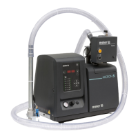
Low level detection system
System for warning and/or monitoring the level of melted adhesive, with a
float detector or capacitive sensor.
Caster system
For 25 and 35l Micron+ machines there is the option to add 4 casters to the
base of the machine to make it easier to move.
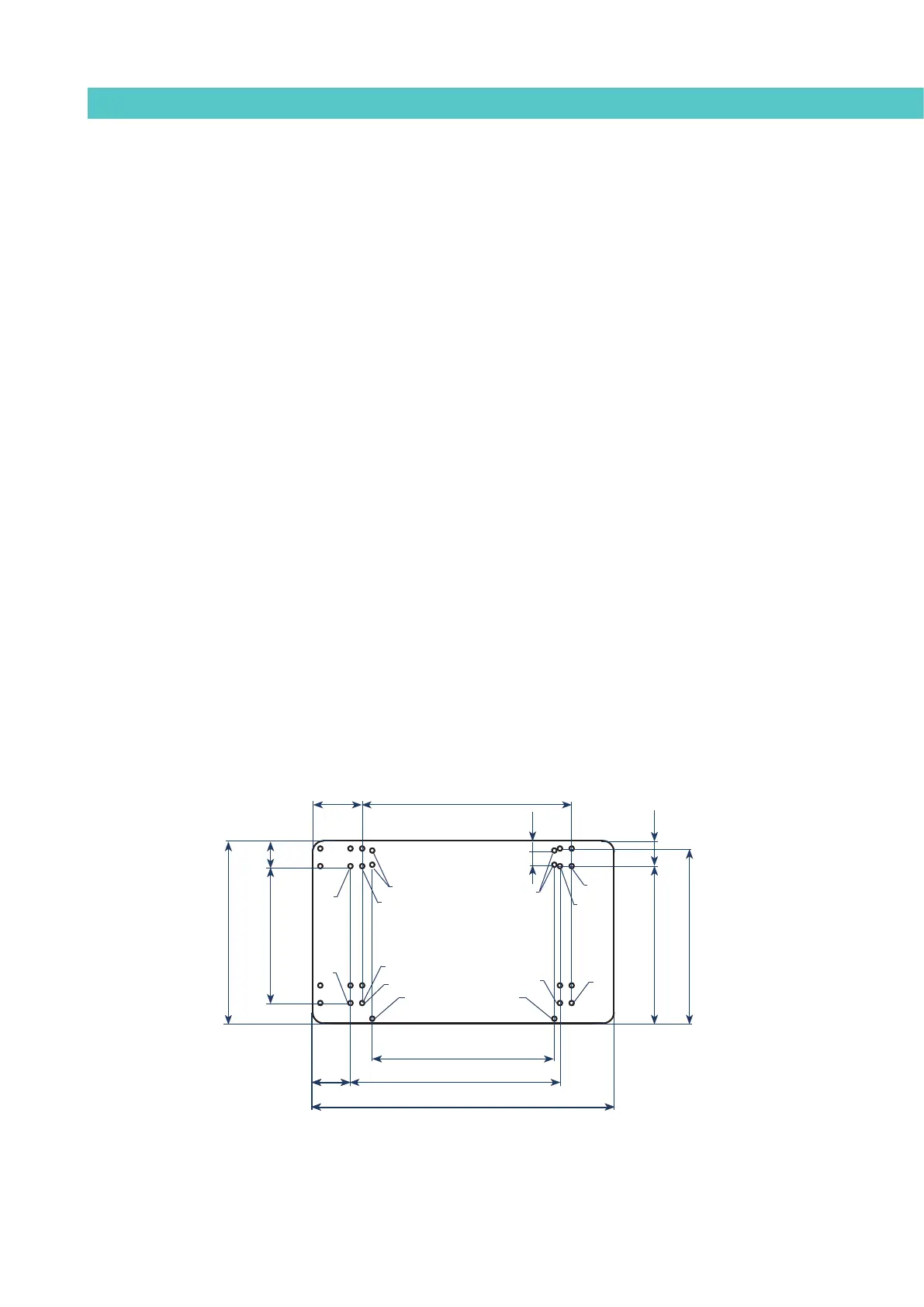
Adaptation plate for previous models
If you want to replace a ‘micron’ 4, 8, or 16 range by new range ‘micron+’ 5,
10, or 20, you can directly change between them if the standard holes was
used to fix the equipment. In this case, the equipment will be outdated a few
centimeters relative to the position of the previous equipment and mooring
table.
To correct this small gap there is an optional adaptation plate to attach the
new units of the range in the above position. This plate is the same for all
units, using the holes indicated depending on the unit (see dimensions below).
For the ‘micron+’ 35 units the adaptation plate does not exist.
A: micron+ 5 unit set up and replacament of other units.
B: micron+ 10, micron+ 20 unit set up and replacament of other units.
C: Replacement of ML-240-ST series units.
D: Replacement of ML-260-ST series units.
VALIDADO/COMFIRM
DIBUJADO/DESIGN
NOMBRE/NAME
FECHA/DATE
TITULO/TITLE
ESCALA/SCALE
REFERENCIA/ REFERENCE
DENOMINACION/DENOMINATION
HOJA Nº/
SHEET NUMBER
D.Z.D.
11/12/2012
15/02/2007
J.Z.G.
515502710
PLACA ADAP MICRON 5-10-20 PISTON A MOD ANT GLV
1 de 1
Este plano es propiedad exclusiva de MELER APLICADORES DE HOT - MELT S.A. Todos los derechos reservados.
This drawing is owned sole of MELER APLICADORES DE HOT- MELT S.A. All rights reserved.
DPTO. OFICINA TECNICA
Agujeros ST
Agujeros para fijar el equipo micron 20 a la placa base.
El uso de estos agujeros permite desplazar el equipo hacia
zonas libres.
Agujeros ST
Agujeros para fijar el equipo micron 10 a la placa base.
El uso de estos agujeros permite desplazar el equipo hacia zonas libres.
Agujeros ST
249
Agujeros para fijar el equipo micron 5 a la placa base.
El uso de estos agujeros permite desplazar el equipo hacia zonas libres.
249
381
548
548
381
332
332
332
381
548
38169
331
38190
548
249 46
280 32
26
16
17.5
306
332
A
A
C-D C-D
A
C-D
Ø 9
B
B
B
B
C-D
A