Introduction to Mellanox SN2000 Spectrum™ Ethernet Switch Systems
Rev 2.2
16Mellanox Technologies
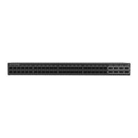
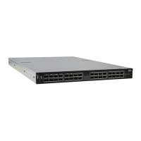
Figure 9: SN2010 Rear Side View
1.2 Speed and Switching
Table 3 describes maximum throughput and interface speed per system model.
*The system can support different interfaces and speed rates using QSFP+ to SFP+ adapters or
hybrid cables. For further information, see
“Splitter (Breakout) Cables and Adapters”.
1.3 Management Interfaces, PSUs and Fans
Table 4 lists the various management interfaces, PSUs and fans per system model.
Table 3 - Speed and Switching Capabilities
System Model 10/25GbE SFP28 Interfaces*
40/50/56/100GbE QSFP28
Interfaces*
Max Throughput
SN2700 64 (using QSFP to SFP splitter
cables)
32 6.4Tb/s
SN2740 64 (using QSFP to SFP splitter
cables)
32 6.4Tb/s
SN2410 Total 64, 48zSFP+ 16 (using
QSFP to SFP splitter cables)
8 4Tb/s
SN2100 64 (using QSFP to SFP splitter
cables)
16 (or 32 50GbE inter-
faces when using QSFP to
2xQSFP splitter cables).
3.2Tb/s
SN2010 34 (using QSFP to SFP splitter
cables)
4 (or 8 50GbE interfaces
when using QSFP to
2xQSFP splitter cables).
1.7 Tb/s
Table 4 - Management Interfaces, PSUs and Fans
System Model USB MGT Console PSU Fan
SN2700 Rear Rear (2 ports) Rear 2 units 4 units
SN2740 Front Front (1 port) Front 2 units 4 units
SN2410 Rear Rear (2 ports) Rear 2 units 4 units
SN2100 Front (mini
USB)
Front (1 port) Front 2 units (non-
replaceable)
4 units (non-
replaceable)
SN2010 Front Front (1 port) Front 2 units (non-
replaceable)
4 units (non-
replaceable)
 Loading...