Installation
Rev 2.2
23Mellanox Technologies
2.2 System Installation and Initialization
Installation and initialization of the system require attention to the normal mechanical, power,
and thermal precautions for rack-mounted equipment.
The installation procedure for the system involves the following phases:
1. Follow the safety warnings in Section 2.1.
2. Pay attention to the air flow consideration within the system and rack - refer to “Air Flow” on
page 23.
3. Make sure that none of the package contents is missing or damaged - see “Package Contents”
on page 25.
4. Mount the system into a rack enclosure - see “19” Systems Mounting Options” on page 25.
5. Power on the system - refer to “Initial Power On” on page 54.
6. Perform system bring-up - see “System Bring-Up” on page 56.
7. [Optional]: FRU replacements are described in Section 2.9 on page 62.
2.3 Air Flow
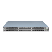
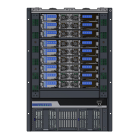
Mellanox systems are offered with two air flow patterns:
• Power (rear) side inlet to connector side outlet - marked with blue power supplies/fans-
FRUs’ handles, as shown in Figure 10.
The rack mounting holes conform to the EIA-310 standard for 19-inch racks. Take
precautions to guarantee proper ventilation in order to maintain good airflow at ambi-
ent temperature.
Unless otherwise specified, Mellanox products are designed to work in an environ-
mentally controlled data center with low levels of gaseous and dust (particulate) con-
tamination.
The operation environment should meet severity level G1 as per ISA 71.04 for gas-
eous contamination and ISO 14644-1 class 8 for cleanliness level
The following information does not apply to SN2100/SN2010. In the SN2100/
SN2010 systems, the fan units are non-replaceable.
 Loading...