Installation
Rev 2.2
40Mellanox Technologies
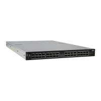
Figure 29: Installation Options
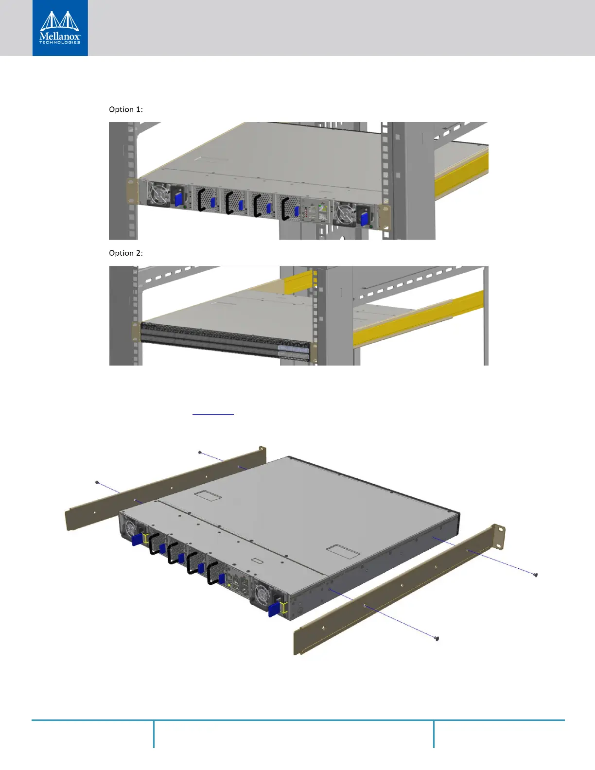
Step 1. Attach the left and right rack mount rails (A) to the switch, and secure the chassis in the rails
by screwing 2 flat head Phillips screws (D) in the designated points on each side (a total of 4
screws). See
Figure 30. To tighten the screws, use a torque of 1.5±0.2 Nm.
Figure 30: Attaching the Rails to the Chassis
Step 2. Install 8 cage nuts (C) in the desired slots of the rack: 4 cage nuts in the non-extractable side
and 4 cage nuts in the extractable side. Note that while each rack U (unit) consists of three
 Loading...