Installation
Rev 2.2
35Mellanox Technologies
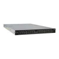
Figure 22: Mounting the Outer Rails into the Rack
Step 3. If cable accommodation is required, route the power cable and/or Eth cable through either
of the outer rails.
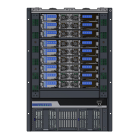
Step 4. Attach left and right inner rails (A+B) to the switch sides, by gently pushing the switch
chassis’ pins through the slider key holes, until locking occurs.
Figure 23: Attaching the Inner Rails to the Switch
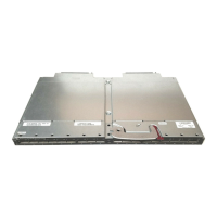
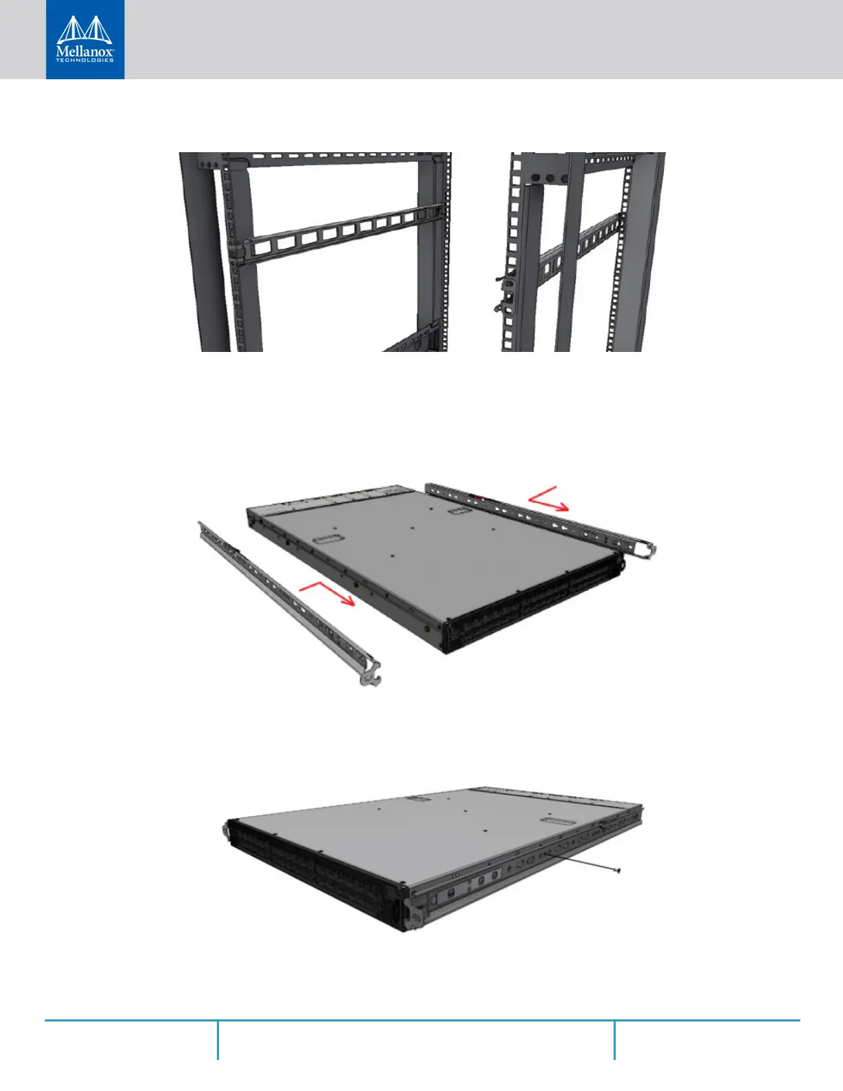
Step 5. Secure the chassis in the inner rails by screwing the 2 flat head Phillips screws (F) in the
designated points with a torque of 1.5±0.2 Nm.
Figure 24: Securing the Chassis in the Inner Rails
Step 6. Slide the switch into the rack by carefully pushing the inner rails into the outer rails installed
on the rack.
 Loading...