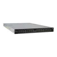
Interfaces
Rev 2.2
73Mellanox Technologies
Table 18 - Fan Status Rear LED Assignments (One LED per Fan)
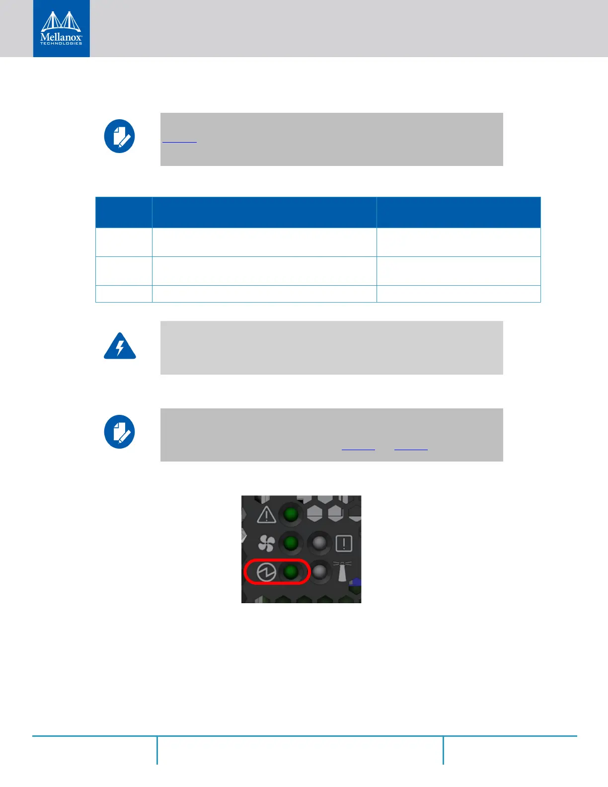
3.2.1.3 Power Supply Status LEDs
Figure 72: Power Status LED
There are two power supply inlets in the system (for redundancy). The system can operate with
only one power supply connected. In case the power supply is an FRU, a second power supply
unit can be added to support hot-swap ability. Each power supply unit has a single 2 color LED
on the right side of the unit, that indicates the status of the unit.
Table 18 does not apply to the SN2100/SN2010 systems.
LED
Behavior
Description Action Required
Solid
Green
A specific fan unit is operating. N/A
Solid Red A specific fan unit is missing or not
operating properly.
The fan unit should be replaced.
Off System boot N/A
Risk of Electric Shock!
With the fan module removed, power pins are accessible within the module cavity.
Do not insert tools or body parts into the fan module cavity.
The following information does not apply to the SN2100/SN2010 systems. In these
systems, the power supply units are non-replaceable, and there is a designated LED
for each unit in the system’s front panel. See Figure 4
and Figure 6.
 Loading...