NetPerformer Hardware Installation Guide
3-18 Memotec Inc.
b. Slide the faceplate out from the chassis wall, and set it aside.
Important: Keep the faceplate for possible reuse at a later time. To limit
electromagnetic interference and ensure optimum ventilation inside the unit’s
chassis, there should be no large openings on the rear panel. If you decide to remove
an interface card at a later time, you will need to replace the faceplate for that slot.
6. Carefully remove the interface card from its protective packaging.
7. Hold the interface card so that the printing on the faceplate is right side up.
8. Insert the card by slowly sliding it into the side rails of the card slot.
► Sliding an FXS or E&M interface card in the TOP interface slot of an
SDM-9140 Series unit:
a. If the bottom interface card slot is empty, remove the faceplate.
OR
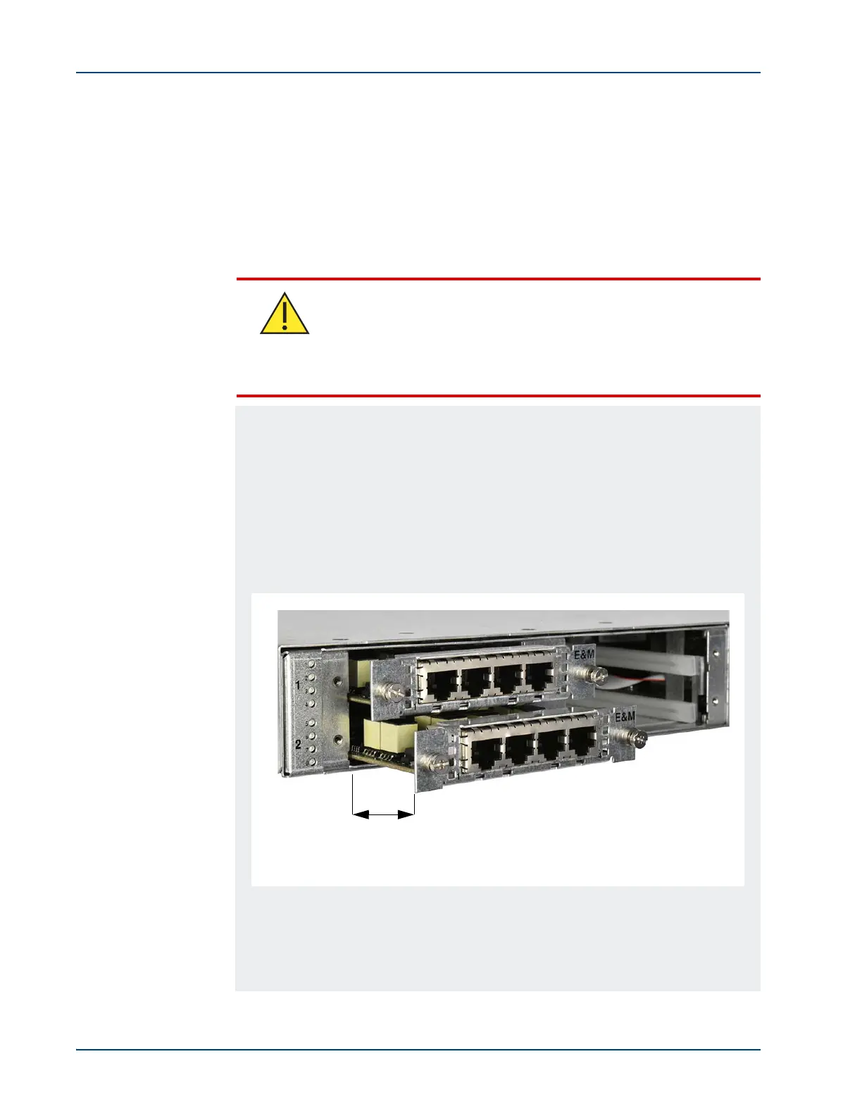
If the bottom interface card slot contains a card, partially remove the
bottom card by sliding it out approximately 3.8 cm or 1.5 inches from
the card slot.
b. Slowly insert the top card into the side rails of the top card slot until it is
fully inserted.
IMPORTANT: When inserting the top card, make sure that the solder side
(bottom) of the card does not interfere with the component side (top) of the
bottom interface card.
Caution
If you are inserting an FXS or E&M interface card into an SDM-
9140 Series unit:
To prevent damage to certain electronic components located under
the FXS and E&M interface cards, use one of the following
methods when inserting them into the TOP or BOTTOM card slots
of SDM-9140 units.
Figure 3-10: Partially Removing the Bottom Card in an SDM-9140 Unit
Approximately 3.8 cm (1.5”)