NetPerformer Hardware Installation Guide
3-32 Memotec Inc.
NOTE: You only need one power connector for normal operation. The second connector
is to connect a redundant power source. When using only one hot-swap power
source, the second slot should have a power supply slot cover.
3.9.2 System Status on Power-Up
On power-up, the SDM-9XXX Series unit executes program decompression, Signaling
Engine software load and system test, which takes less than one minute to complete. You
can follow the status of the initialization sequence from the console (see next section), or
by watching the front or rear panel LEDs.
Table 3-4
shows the various front panel LED states that occur during the NetPerformer
startup sequence (after a power-on or software reset).
NOTE: The entire startup sequence is executed within 30 seconds. Some of its stages
are brief, and may be difficult to distinguish from the rest. Refer also to “System
Status LEDs” on page 4-11.
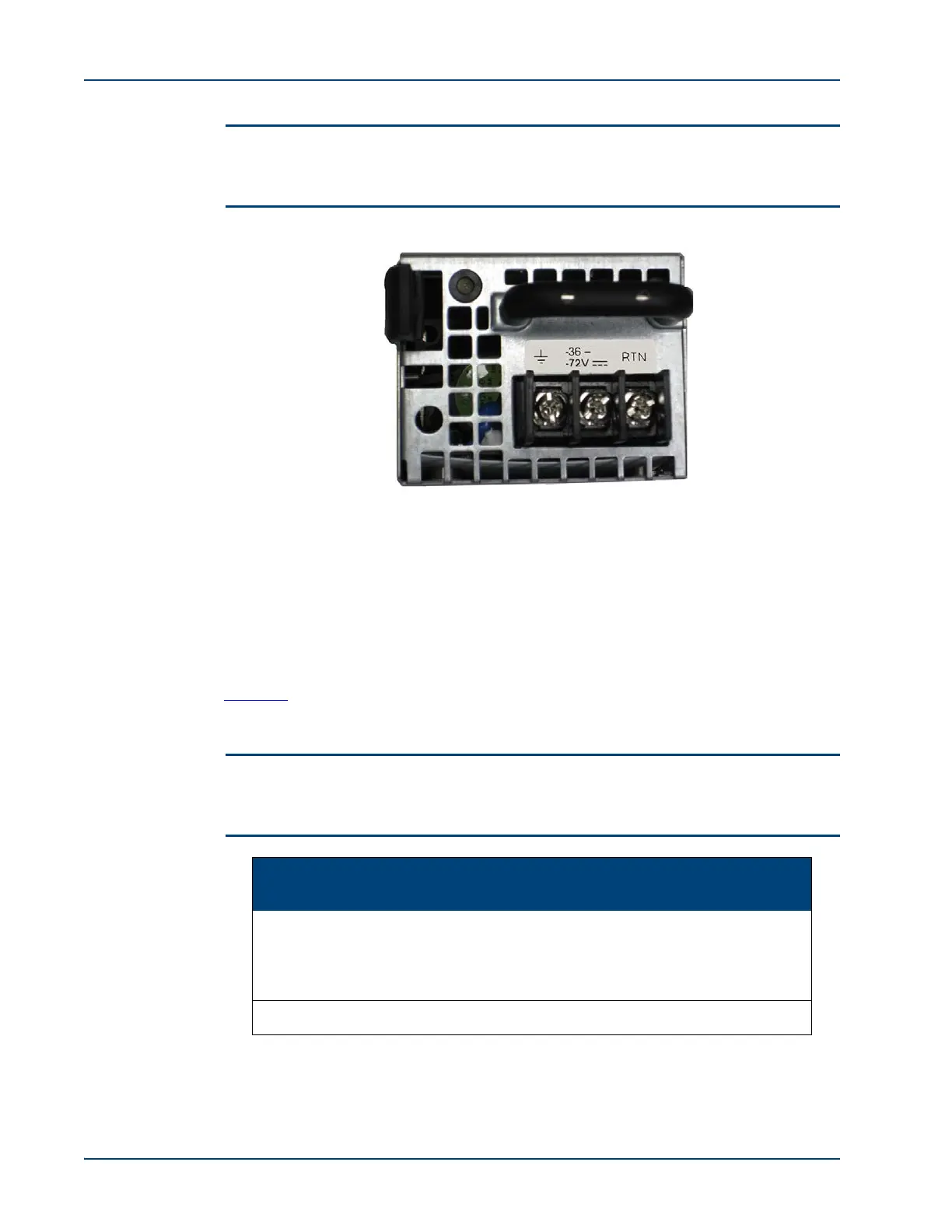
Figure 3-20: DC Power Supply
Stage PWR ST AL
Current Status of the SDM-9XXX Series
Unit
1 green blink blink
Quick hardware test by the bootstrap.
Blinking and frequent changes of the
STATUS and ALARM LEDs occur during this
stage
2 green red green Hardware initialization by the bootstrap
Table 3-4 Front Panel LED States During System Startup