MC³ 24.96.EX O&M Manual Page 40 08/14/01 4:34 PM/LDD
Logical Input Physical Input
Start a Batch Rack 2 Input 1
Stop the Batch Rack 2 Input 2
Clear the Batch Rack 2 Input 3
Diverter Valve Rack 1 Input 3
EMT Enabled Always On
Total Enabled Always On
Sub Total Enabl Always On
Zero Tracking Always On
Available I/O 1-8 Always Off
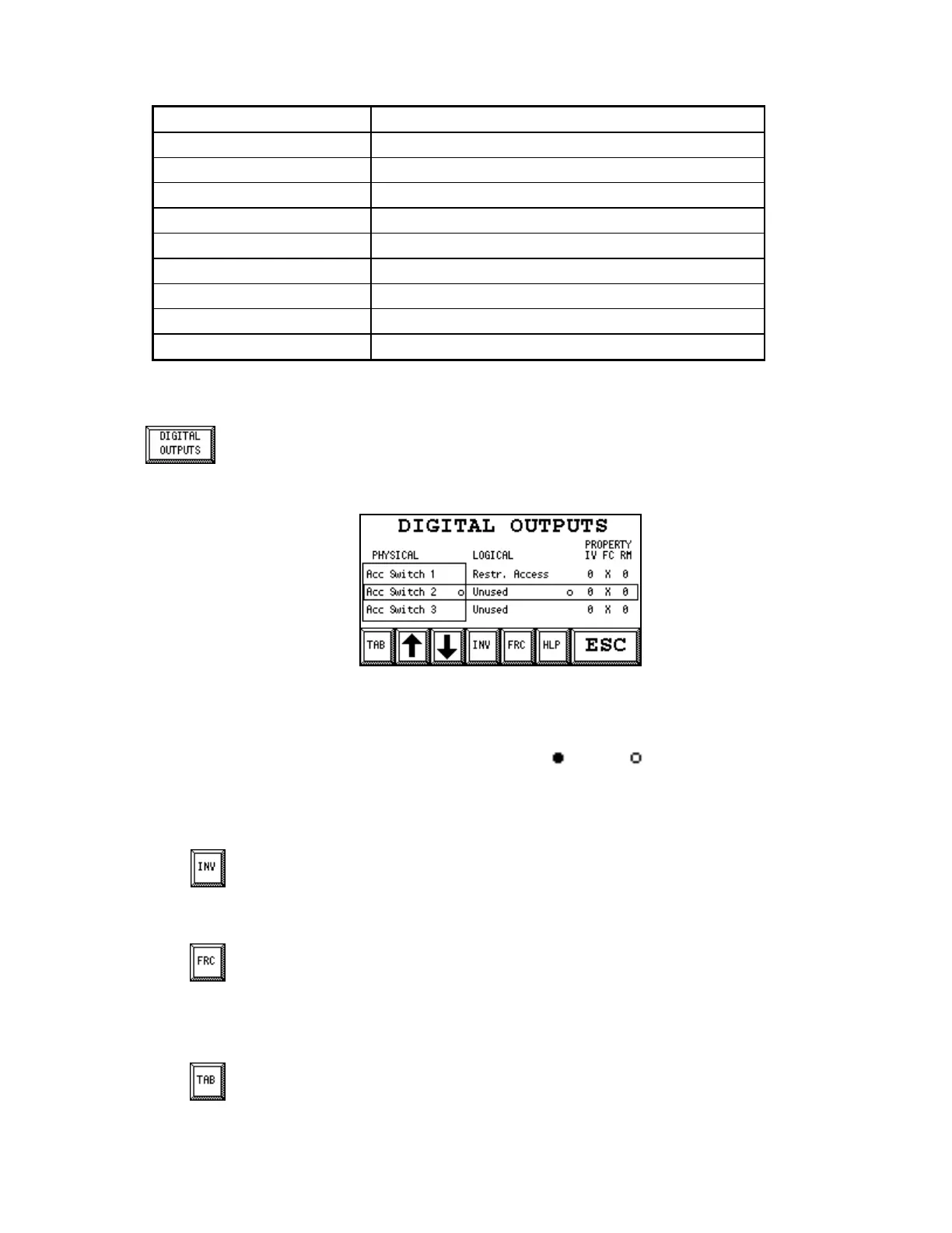
Digital Outputs
You reach the Digital Outputs screen from Setup Screen 2. See page 33. The screen
allows you to change the mapping for the Digital Outputs. The Logical Outputs are
mapped to the Physical Outputs. The Physical Outputs appear to the left, and the
Logical Outputs appear to the right. When you enter the screen, the list of Physical
Outputs is marked.
Digital Outputs setup screen
Use the up and down arrow key the select the physical output you want to work with. Map unused
physical outputs to either “Always On” or “Always Off”. The black dot to the right of the Physical
Output name indicates the state of the Physical Output. (ON) or (OFF). The black dot to the
right of the Logical Output name indicates the state of the Logical Output. In the IV (inverted)
property column, a “0” means “Not Inverted” and a “1” means “Inverted”. In the FC (forced)
property column, a “0” means “Forced OFF”, a “1” means “Forced ON” and an “X” means “Not
Forced”. The “RM” property column has no meaning and is not used.
INV (button) / RV (indication)
This button inverts the Physical Output. The character the “IV” column will toggle
between “0” (not inverted) and “1” (inverted). The changes take effect immediately.
FRC (button) / FC (indication)
This button controls forcing of the Physical Output. The character in the “FC” column
will cycle between “X” (not forced), “0” (forced OFF) and “1” (forced ON). The changes
take effect immediately. The physical inputs “Always On” and “Always off” can not be forced.
TAB
This button switches the marking between the Physical and Logical columns. Touching
the TAB button makes the screen look like this: