MC³ 24.96.EX O&M Manual Page 69 08/14/01 4:34 PM/LDD
PCIO BOARD
1 2 3 4 5 6
Digital I/O2 Digital I/O1
AOUT 1 AOUT 2 AIN 1
+ + +
---
1
2
15
16
1
2
15
16
O
U
T
4
O
U
T
5
O
U
T
6
O
U
T
7
O
U
T
8
O
U
T
3
O
U
T
2
O
U
T
1
G
N
D
+
5
V
D
C
G
N
D
I
N
4
I
N
1
I
N
2
I
N
3
+
5
V
D
C
15
1
3
5
7
9
11
13
2
4 6 8 10 12
14 16
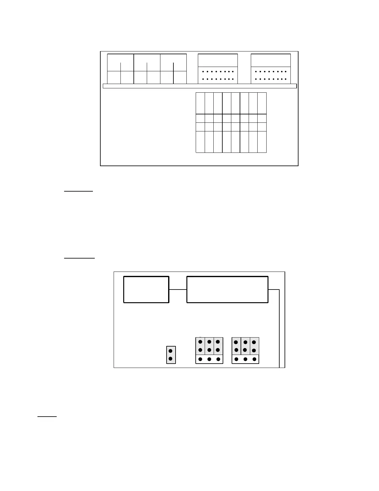
Digital I/O Pin Layout
Digital I/O
Digital Inputs
The digital inputs are provided so that the customer may provide logical on/off signals to the MC
³
Controller. The default digital input is:
Digital Outputs
The digital outputs are provided so that the customer may use these outputs as status indicators.
The default digital output map is:
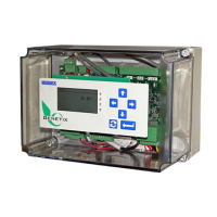
Analog I/O
Located on the PCIO board are straps to convert the analog signals from current to voltage.
Strap top row for current out
Strap bottom row for voltage out
Strap for
Current Input
Ana Out 2 Ana Out 1
Analog IO ConnectorDigital Rack 2
This example is set for Current input and output.
Analog Inputs
One analog input is available for changing the Setpoint. See “Analog Input” on page 33.
NOTE: If the analog signal is a current input then a jumper must be installed. If the input is a voltage, a
jumper must be removed for proper conversion.