MC³ 24.96.EX O&M Manual Page 41 08/14/01 4:34 PM/LDD
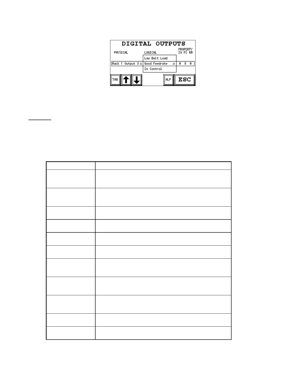
Digital Outputs setup screen, Logical list marked
The INV and FRC buttons become invisible. Use the up and down arrow key to change the
mapping for the Physical Output.
CAUTION: As you move through the Logical Outputs with the up and down arrow keys, the Physical
Output will immediately change state, following the state of the selected Logical Output.
Touching the TAB button again restores the marking to the Physical column.
List of Logical Outputs
There are many logical outputs. You normally only use a few of them.
Logical Output Description
High Rate Alarm High Feedrate Alarm. The function depends on the Limit
Switch Mode setting. See Limit Switches on page 26. Action is
delayed according to the High Delay parameter.
Low Rate Alarm Low Feedrate Alarm. The function depends on the Limit Switch
Mode setting. See Limit Switches on page 26. Action is
delayed according to the Low Delay parameter.
High Feedrate Feedrate is above High Feedrate. See Limit Switches on page
26. Not delayed.
Low Feedrate Feedrate is below Low Feedrate. See Limit Switches on page
26. Not delayed.
High Belt Load Belt Load is above Overload Limit. See Limit Switches on page
26. Not delayed.
Low Belt Load Belt Load is below Underload Limit. See Limit Switches on
page 26. Not delayed.
Good Feedrate This output follows the GOOD indicator in the Main Screen. It
is normally used as a startup sealing contact. See Indicators (
on Feeder Screen) on page 11.
In Control The controller is running in automatic mode, and no calibration
routines (with the exeption of the Grab Sample routine) are
active.
Feeder Running This output is intended for the belt motor starter. The
application will turn this output on whenever the Feeder Belt
should be running.
General Alarm There is at least one General Alarm condition. See General
Alarms on page 12.
Analog Setpoint The Feedrate Setpoint Mode is either “Rem Ana” or “Rem
Ratio”. See Feedrate setpoint on page 16.