MC³ 24.96.EX O&M Manual Page 43 08/14/01 4:34 PM/LDD
Physical Output Description
Rack 1 Output 1 through 8 PCIO #1 1
st
bank.
Rack 2 Output 1 through 8 PCIO #1 2
nd
bank.
Rack 3 Output 1 through 8 PCIO #2 1
st
bank.
Rack 4 Output 1 through 8 PCIO #2 2
nd
bank.
Vol Switch 1 through 8 Volatile Switches
Acc Switch 1 through 8 Accessory Switches
Internal I/O 1 through 24 Internal I/O Points
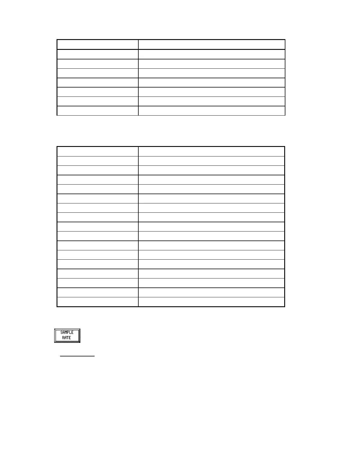
List of Default Output Settings
Physical Output Logical Output
Rack 1 Output 1 High Rate Alarm
Rack 1 Output 2 Low Rate Alarm
Rack 1 Output 3 Good Feedrate
Rack 1 Output 4 In Control
Rack 1 Output 5 Feeder Running
Rack 1 Output 6 Discharge Gate
Rack 1 Output 7 General Alarm
Rack 1 Output 8 Z Tracking High
Rack 2 Output 1 High Feedrate
Rack 2 Output 2 Low Feedrate
Rack 2 Output 3 High Belt Load
Rack 2 Output 4 Low Belt Load
Rack 2 Output 5 Manual Setpoint
Rack 2 Output 6 PID Off Limits
Rack 2 Output 7 Belt Slippage
Rack 2 Output 8 Unused
Sample Rate
There are two modes of sample rates in the MC³ 24.96.EX Controller, Internal and External.
Internal mode is almost always used. In external mode, the sampling is triggered by tacho 1, using
the parameters described below.
Internal Sample Rate Parameters
The Sample Time is the interval, in seconds, between samples read from the Load Cell A/D
converter. Limits are minimum of 0.10 and a maximum of 5.0. Default is 0.33.