MC³ 24.96.EX O&M Manual Page 68 08/14/01 4:34 PM/LDD
WORKING WITH INPUTS AND OUTPUTS
The MC
³
is capable of processing many different types of inputs and outputs. Most of the
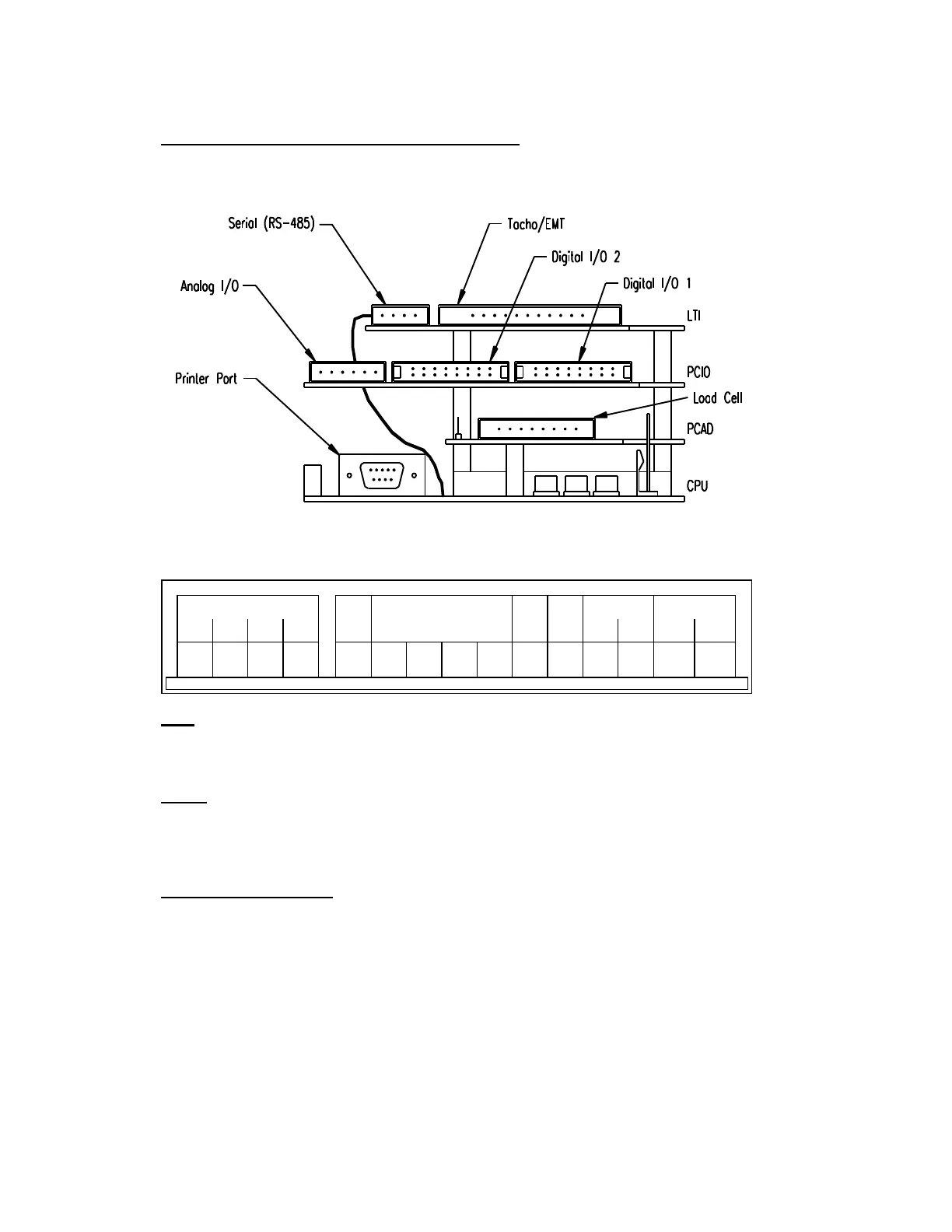
connections necessary for the inputs and outputs are located on the Backplane Board. Please
refer to the electrical connection diagram for the physical layout of all input and output connections.
Rear View (standard configuration)
LTI BOARD
1 2 3 4 1 2 3 4 5 6 7 8 9
TX+ TX- RX+ RX-
GND
1A 1B 2A 2B
+12V
DC
+5V
DC
10 11
AC EMT
-
+
Tacho
RS-485
DC EMT
A B
EMT
The EMT outputs are provided to you for connection to a remote totalizer. Both AC and DC pulse
outputs are available. See “External Totalizer Parameters” on page 44 for more information.
Tacho
If only one tacho input is to be used it must be in the A position. The mode should be No -
Direction.
See Tachometer Parameters on page 29 for more information regarding tacho parameters.
Serial Communications
Serial Channel #1 is an RS-485 port. The baud rate, parity, stop bit settings and protocol of the
ports are setup in the software. For further information on configuring the Serial Communications
Board and its interface to different types of serial equipment, see Communications on page 44.