■■■■■■■■■■■■■■■■■■■■■■
Table of figures
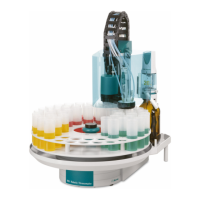
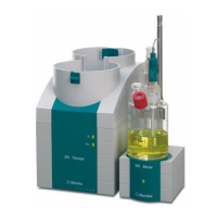
858 Professional Sample Processor
■■■■■■■■
V
Table of figures
Figure 1 Front 858 Professional Sample Processor ........................................... 8
Figure 2 Rear 858 Professional Sample Processor ............................................ 9
Figure 3 Connector strip 858 Professional Sample Processor .......................... 10
Figure 4 Sample rack with sample vessels ...................................................... 10
Figure 5 Attaching a sample rack .................................................................. 11
Figure 6 Swing Head - Configuration data ..................................................... 13
Figure 7 Peristaltic pump ............................................................................... 14
Figure 8 Injection valve ................................................................................. 15
Figure 9 Fill / Inject ........................................................................................ 15
Figure 10 Connecting the Swing Head ............................................................ 16
Figure 11 Mounting the retaining plate ........................................................... 18
Figure 12 Installing the filtration cell holder / Dosino holder ............................ 18
Figure 13 Mounting the Dosino ...................................................................... 19
Figure 14 6.1618.020 Thread adapter ............................................................. 19
Figure 15 6.2001.070 Stand plate ................................................................... 20
Figure 16 Mounting the support rod ............................................................... 20
Figure 17 Mounting the stand plate ................................................................ 21
Figure 18 Mounting the stirrer and the dilution vessel ..................................... 22
Figure 19 Mounting the cross strut ................................................................. 22
Figure 20 Fixing the support rod ..................................................................... 23
Figure 21 Installing the needle ........................................................................ 25
Figure 22 Mounting the safety shield .............................................................. 27
Figure 23 Rod stirrer 802 Stirrer ...................................................................... 27
Figure 24 Magnetic stirrer 741 Stirrer .............................................................. 27
Figure 25 Connecting the tower stirrer ............................................................ 28
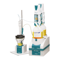
Figure 26 772 Pump Unit ............................................................................... 28
Figure 27 823 Membrane Pump Unit .............................................................. 28
Figure 28 Connecting pumps .......................................................................... 29
Figure 29 Installing the pump tubing .............................................................. 30
Figure 30 Inserting the tubing cartridge .......................................................... 31
Figure 31 Connecting the computer ................................................................ 33
Figure 32 MSB connections ............................................................................ 35
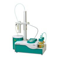
Figure 33 Connecting a dosing device ............................................................. 36
Figure 34 Connecting an MSB stirrer ............................................................... 37
Figure 35 Connecting the rod stirrer to the titration stand ............................... 37
Figure 36 Connecting the Remote Box ............................................................ 38
Figure 37 USB connectors ............................................................................... 39
Figure 38 Pump tubing connection – Replacing the filter ................................. 41
Figure 39 Connectors of the Remote Box ........................................................ 45
Figure 40 Pin assignment of remote socket and remote plug ........................... 45