CDP301 Dew-Point Tester User’s Manual
8 97585 Issue 1, June 2020
INSTALLATION
2.4 Gas Sample Connections
The following points should be considered when installing the sample gas supply line:
• PTFE tape is recommended for pipe connections.
• Solvent-based pipe thread sealant should not be used, as condensable
components or contaminates can be leached during the curing period.
Care and attention to the position and installation of the tubing will minimize problems
caused by avoidable contamination. The most common issue with sample ow is the
accumulation of liquid in impulse lines during a shutdown period. If the measurement
system has not been isolated, condensate can be displaced, on re-start, into components
and associated tube work. An optional CDP301 sample system is available from Michell
Instruments:
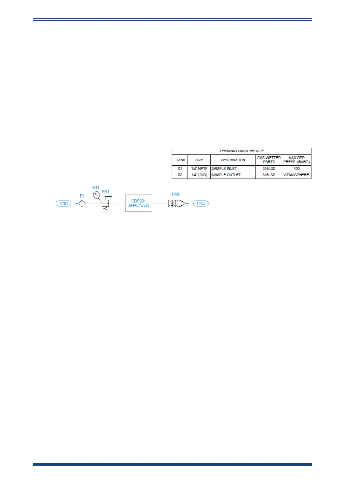
Figure 2
Michell Sample System
2.4.1 Connecting the Michell Sample System (optional accessory)
DO NOT permit pressures greater than the specied safe working pressure of
100 barg (1450 psig) to be applied directly to the instrument.
Ensure the instrument is properly secured before use, i.e. tripod mounted or
tted to a suitable benchtop mounting.
1. Ensure the isolation valve to the sample tapping point is fully closed.
2. Connect the Michell sample system to the CDP301 inlet and outlet
connections and tighten the ttings.
3. Ensure pressure regulator PR1 is fully closed.
4. Connect the sample tapping point to the sample system using suitable
stainless steel tubing or high-pressure rated hose (such as Swagelok B
series).
5. Connect the vent line (if available) to the owmeter’s 1/4” FNPT outlet
connection and ensure the isolation valve (if tted) is fully open.
6. Refer to Section 4, SYSTEM START-UP AND MEASUREMENT PROCEDURE,
for tester operation.