Installation, Programming and Maintenance Microdos Pooltec
Rev. 1.0 EN
8
3. MICRODOS POOLTEC SYSTEM INSTALLATION
3.1. PLUMBING
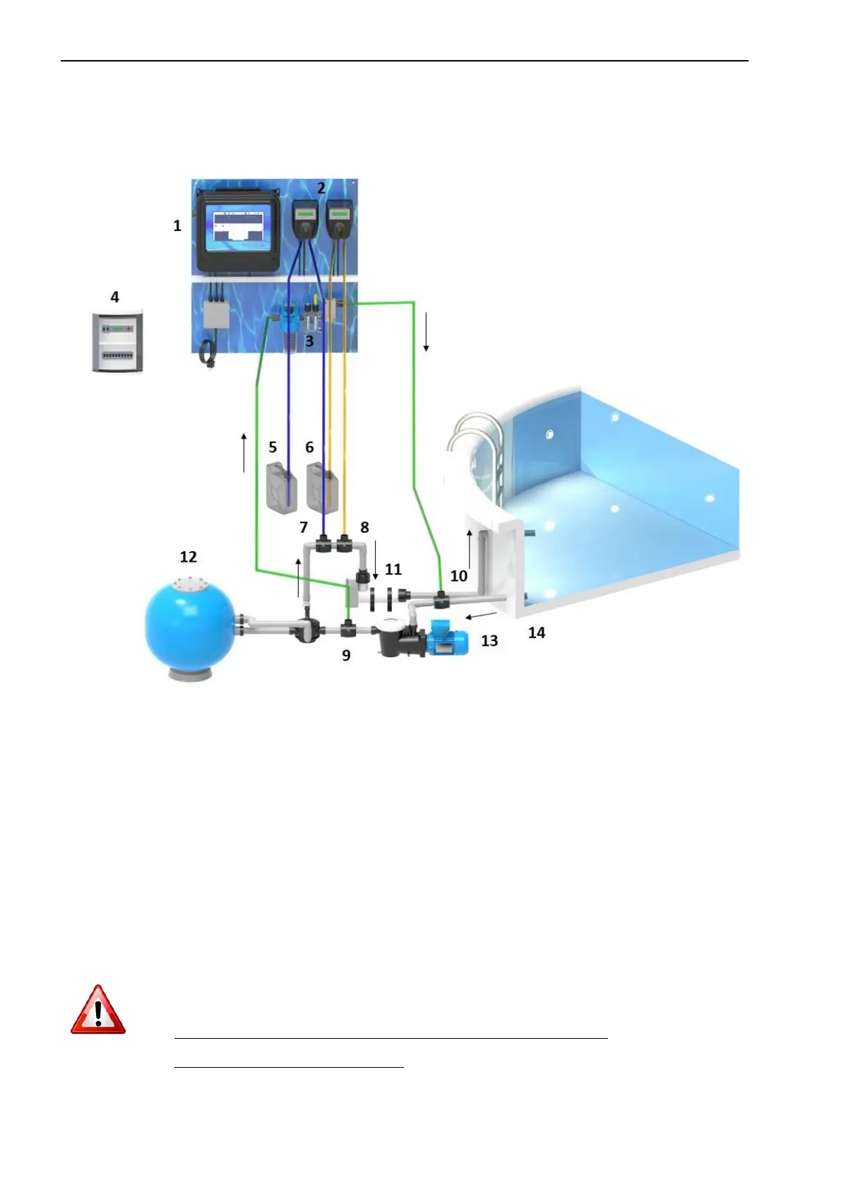
ORIENTATIVE DIAGRAM
1. Control unit 5. pH tank 9. Inlet water 13. Recirculation pump
2. Peristaltic/solenoid pumps 6. Chlorine tank 10. Outlet water 14. Swimming pool
3. Analysis group 7. pH injection 11. Heat pump
4. Electric panel 8. Chlorine injection 12. Filter
3.1.1. CONTROL UNIT INSTALLATION
Fix the
control unit AT LESS THAN 3 METERS and dosing pumps to the wall close to the compartment, near the product deposits.
3.1.2. PROBES AND INJECTIONS
For installation of the pH probe and injection canal, you should use the probe-holder.
Do not leave the system without water when probes are installed. If pH or RX probes dry out, they will be
damaged and cannot be used.
For maintenance of the chlorine probe, consult the manual of the chlorine probe.
USE OF SULPHURIC ACID AS PH REDUCER.
USE OF CHLORIDRIC ACID, DRASTICALLY REDUCE THE LIFETIME OF THE SILICON INJECTION PIPES