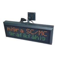
migra Ethernet/IP
Large Format, Graphics Compatible Display with Ethernet/IP Interface
Page 14
microSYST Systemelectronic GmbH, Am Gewerbepark 11, 92670 Windischeschenbach
+49 9681 91960-0, +49 9681 91960-10, info@microsyst.de, www.microsyst.de
3.7 General Frame Description
The frames to be transmitted to the display have the following structure:
Length byte = frame length
See chapter “Online Frame Layout”
*0: Toggle byte:
The toggle byte must be increased by 1, if the frame shall be processed
However the toggle byte must only be changed if the lock-byte = 0 (see chapter
“General Frame Description”). Otherwise there is a lock from the configuration
software MICON (because it controls the display at the moment).
The lock-byte is read from address 0x3FE of the display interface (with “explicit
messaging”).
The transmit-bytes are written as of the address 0x202 into the display
interface.
Response Frame:
The display writes the response frame as of the address 0x160.
Length byte = frame length
See chapter “Response Frame”

 Loading...