VetPro DC Installation/Service Manual, 00-02-1606, Revision R01
107
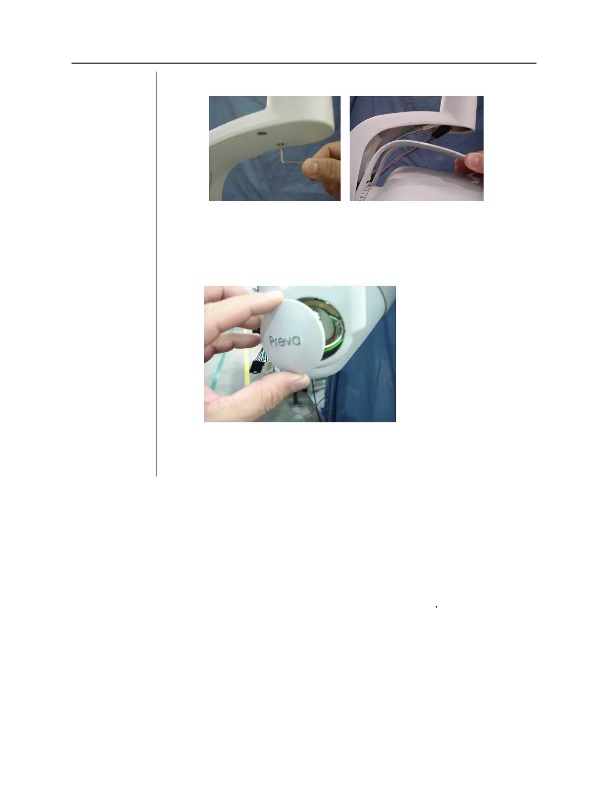
34. Mount the yoke cover that was removed in (Step 4)
35. Check to ensure the wires are
binding when you rotate the
tubehead completely clockwise or completely counter clockwise. The
cabling should expand and contract cleanly and evenly without any
binding.
36. Place the cap back on the tubehead.
37. Proceed with the automated calibration found on page 72 if Logic PCB
firmware revision is 5.0 or lower.