VetPro DC Installation/Service Manual, 00-02-1606, Revision R01
29
Unit Front Cover
1. Open the shipping carton and locate the Control Unit in the first level of the
carton.
2. Remove the Phillips screw from the front cover of the Control Unit.
3. Carefully remove the front cover.
4. Place the front cover and the screw in a safe location for later reassembly.
the Control Unit
1. Select the 3/8” x 3” long lag screws [30-H0006] and washers [30-H0008]
.
Note:
For concrete walls, the installer must supply the appropriate
mounting bolts.
2. Put a lag screw and washer through the upper mounting hole of the Control
Unit.
3. Place the Control Unit on the wall and loosely tighten the upper mounting
bolt.
4. Put the remaining lag screw and washer through the lower mounting hole of
the Control Unit and loosely tighten. Be sure that the power wire extends
through the opening at the bottom of the Control Unit.
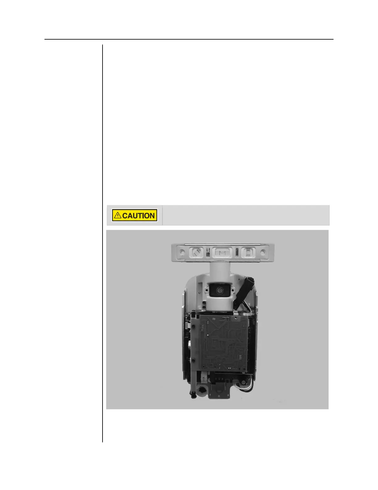
5. Place a level on the Control Unit bearing parallel to the wall, as shown in
Figure 14. Level the Control Unit.
6. Tighten the upper and lower lag screws to 14–18 lb-ft (2.0 to 2.5 m-kgs).
.
Do not over-tighten the lag screws. Over-tightening them will
damage the wooden stud and reduce the holding force.
Figure 15
Leveling the
Control Unit
7. Drill a hole for a #12 wood screw below the lower lag screw, as shown in
Figure 15. Install and tighten the wood screw to prevent the unit from
shifting.