VetPro DC Installation/Service Manual, 00-02-1606, Revision R01
41
Articulating Arm
Brake Assembly
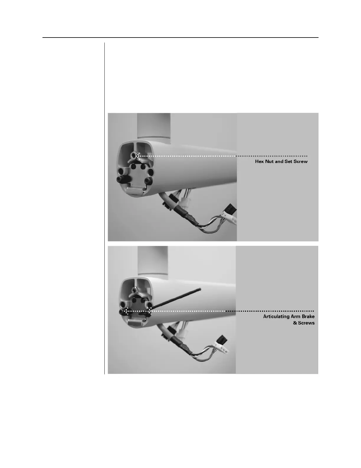
1. Locate the Articulating Arm brake assembly (30-A2068).
2. Insert the M6 x 25 mm long set screw, as shown in
Figure 24
. Using a 3
mm hex key, tighten the screw fully than back off ¼ turn and secure with
the hex nut.
3. Using a 3 mm hex key, install the Articulating Arm brake. Tighten screws
until the Articulating Arm brake comes into contact with the shaft of the
Articulating Arm. If additional friction is required to prevent drifting, turn
the two screws evenly ~¼ turn at a time until drift stops, as shown in
Figure 25
Installing the Hex
Nut and Set Screw
Figure 26
Adjusting the
Articulating Arm
Brake Assembly