VetPro DC Installation/Service Manual, 00-02-1606, Revision R01
66
Dual Switch
Note: This configuration uses two cables. One connects the VetPro DC to the
first switch and the other connects the first switch to the second switch.
1. Route one cable from the VetPro DC to the first switch location either
through conduit or on the surface of the wall.
2. Route the other cable from the first switch location to the second switch
location either through conduit or on the surface of the wall.
3. Thread the first cable end with the handset connector through the opening
in the wall mount cover from the inside and connect it to the Operator Panel.
If the cable is routed on the surface of the wall, it should enter the wall
mount cover through the notch on the left of the power switch.
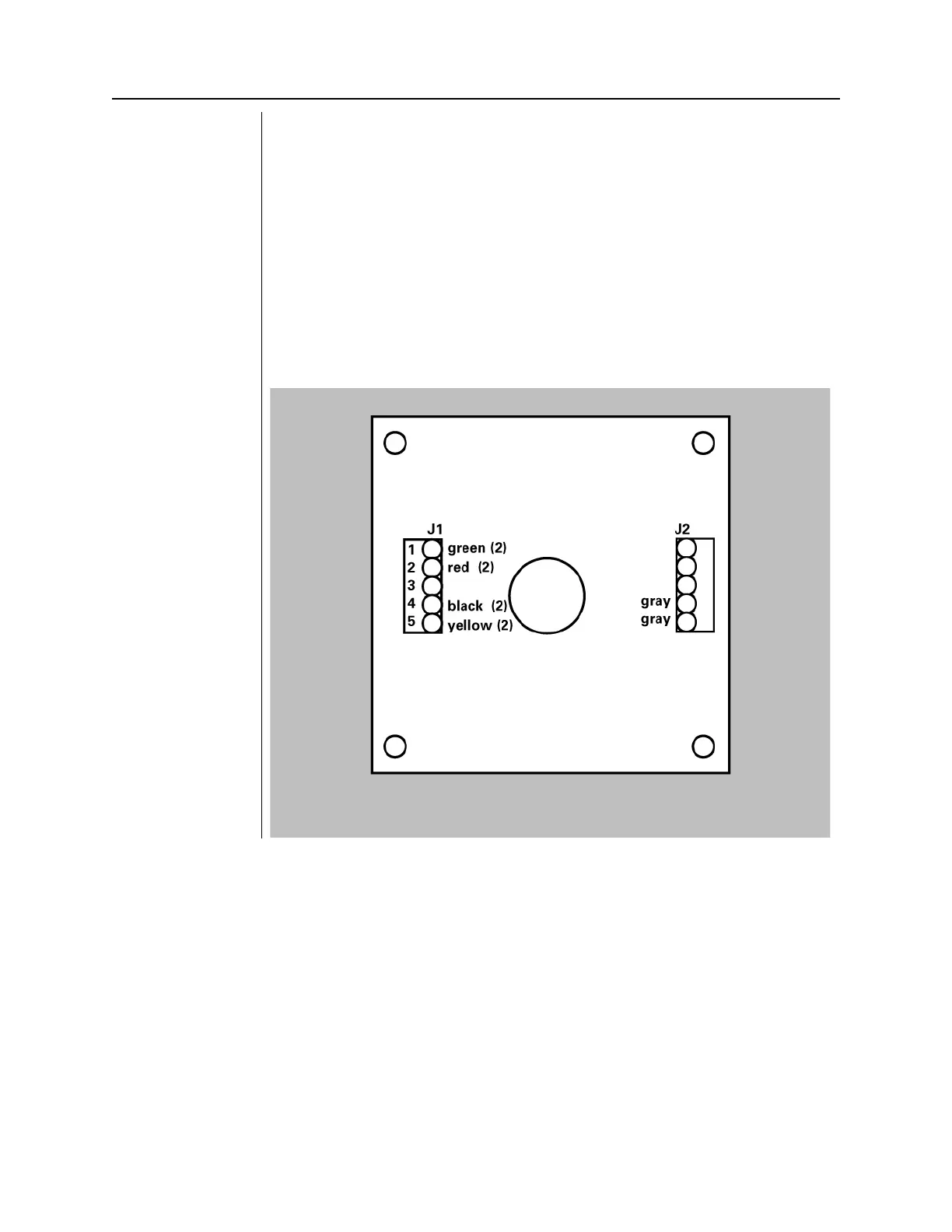
4. For a parallel connection, connect the cable conductors of both cables to
terminal block J1 on the PCB of switch enclosures #1 as shown in Figure
47
. The (2) indicates that two green wires will join together in terminal 1 of
J1, etc. For a series connection, connect the wires as shown in Figure 48.
Figure 49
Parallel Switch
Configuration