Technical Information
6
G1000 / G2000 Dishwashers
G1000 / G2000 Dishwashers - List of Figures
Figure 1-1: Appliance Overview (Typical Integrated Unit)............................................. 11
Figure 1-2: Appliance Overview (Typical Fully Integrated (Vi) Unit) ............................. 12
Figure 1-3: Pre-Finished Dishwasher............................................................................ 14
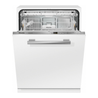
Figure 1-4: Integrated Dishwasher................................................................................ 14
Figure 1-5: Fully Integrated (Incognito) (Vi) Dishwasher............................................... 15
Figure 1-6: Dimensions ................................................................................................. 17
Figure 1-7: Data Tag Location ......................................................................................18
Figure 1-8: Data Tag Information .................................................................................. 18
Figure 1-9: Model Numbering .......................................................................................19
Figure 1-10: Layout of Components................................................................................ 21
Figure 2-1: Installation Manual (Typical) ....................................................................... 22
Figure 3-1: Door Handle Release .................................................................................23
Figure 3-2: Child Safety Lock........................................................................................ 23
Figure 3-3: Salt Container Release............................................................................... 25
Figure 3-4: Filling the Salt Using the Built In Funnel..................................................... 25
Figure 3-5: Display (Main Menu)................................................................................... 26
Figure 3-6: Display (With Selected Program)................................................................ 26
Figure 3-7: Display (With Selected Options) ................................................................. 27
Figure 3-8: Display (Main Menu)................................................................................... 27
Figure 3-9: Display (With Selected Program)................................................................ 27
Figure 3-10: Display (With Selected Options) ................................................................. 28
Figure 4-1: Inner Cabinet .............................................................................................. 29
Figure 4-2: WaterProof System Intake Valves .............................................................. 30
Figure 4-3: WaterProof System Flow Restrictor............................................................ 31
Figure 4-4: Water Inlet Mixer......................................................................................... 33
Figure 4-5: Inlet Mixer without EGS .............................................................................. 35
Figure 4-6: Inlet Mixer with EGS ................................................................................... 36
Figure 4-7: Inlet Mixer during Reactivation ...................................................................37
Figure 4-8: Water Intake and Circulation Paths ............................................................ 41
Figure 4-9: Circulation Pump – Water Paths................................................................. 42
Figure 4-10: Circulation Pump - Components................................................................. 44
Figure 4-11: Heater Pressure Switch Circuit................................................................... 47
Figure 4-12: Turbidity Sensor Circuit ..............................................................................48
Figure 4-13: Turbidity Sensor.......................................................................................... 49
Figure 4-14: Spray Arm Sensor ......................................................................................50
Figure 4-15: Filter Combination in Sump ........................................................................51
Figure 4-16: Combination Dispenser ..............................................................................52
Figure 4-17: Drying System UTT Version 1 .................................................................... 54
Figure 4-18: Drying System UTT Version 2 .................................................................... 56
Figure 5-1: Toe Kick (Plinth) Removal .......................................................................... 75
Figure 5-2: Door Tension Adjustment ........................................................................... 62
Figure 5-3: Side Panel Removal ................................................................................... 59