Technical Information
4
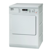
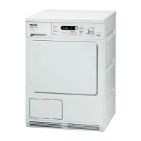
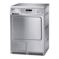
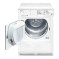
T 80xx
3.7 F1 - Short Circuit in Heater Bank NTC (2R30) ............................ 51
3.8 F2 - Open Circuit in Heater Bank NTC (2R30) ............................ 51
3.9 F3 - Short Circuit in Fill-Ring NTC (1R30) ................................... 52
3.10 F4 - Open Circuit in Fill-Ring NTC (1R30) ................................... 52
3.11 F41 - Electronic Fault (Faulty EEPROM/Faulty Data) .................. 53
3.12 F43 - Wrong Model Detected ....................................................... 53
3.13 F50 - Drive Stalls and Heater Is On for 3 Seconds ...................... 53
3.14 F55 - Overriding Time Limit Exceeded, Approximately 180
Minutes ........................................................................................ 54
3.15 F66 - Air Leakage ........................................................................ 55
3.16 Laundry is Overdried/F55 (Overriding Time Limit Exceeded) ...... 55
3.17 Appliance Not Functioning/Wrong Version Detected ................... 55
4 Service ..................................................................................................... 56
4.1 Programming Mode Summary ..................................................... 56
4.2 Activating/Deactivating the Demonstration Mode ........................ 57
4.3 Service Mode Summary .............................................................. 58
4.4 Removing the Fascia Panel ......................................................... 61
4.5 Control/Power Electronic Removal .............................................. 61
4.6 Electronics Support Bracket (Plastic) Removal ........................... 62
100 Electrical Components .......................................................................... 64
4 Service ..................................................................................................... 64
4.1 Heater Relay (1K1/1, 2K1/1) Removal ........................................ 64
4.2 RemoteVision Module Removal .................................................. 64
110 Technical Service Bulletins ................................................................... 65
1 Dryer Venting Information ........................................................................ 65
2 Laundry Detergent Notice: Purex Complete 3-in1 Laundry Sheets ......... 67
3 Dryer Duct Length ................................................................................... 67
4 5.5-Kilo Dryer Electrical Requirements .................................................... 70
List of Figures
Figure D-1: Optical Interface for MDU ............................................................................. 10
Figure D-2: T 8002/T 8003/T 8005 Component Layout .................................................. 11
Figure D-3: T 8012 C/T 8013 C Component Layout ....................................................... 12
Figure D-4: T 8019 CI Component Layout ...................................................................... 13
Figure D-5: T 8023 C Component Layout ....................................................................... 14
Figure 010-1: Lid Removal .............................................................................................. 15
Figure 010-2: Metal Support Bracket .............................................................................. 17
Figure 020-1: Door Panel Retainers ............................................................................... 19
Figure 020-2: Door Cap Screws ...................................................................................... 19
Figure 020-3: Door Lock Removal .................................................................................. 20
Figure 030-1: Heater Bank Removal ............................................................................... 26
Figure 030-2: Similar illustration. Some models have only one temperature limiter. ...... 27
Figure 030-3: Bearing Housing Attachment .................................................................... 28
Figure 030-4: Rear Bearing ............................................................................................. 28
Figure 030-5: Residual Moisture Sensor ......................................................................... 29
Figure 040-1: Drive/Fan - T 8002, T 8003, T 8005 ......................................................... 30
 Loading...