Technical Information
32
T 980x/T 982x
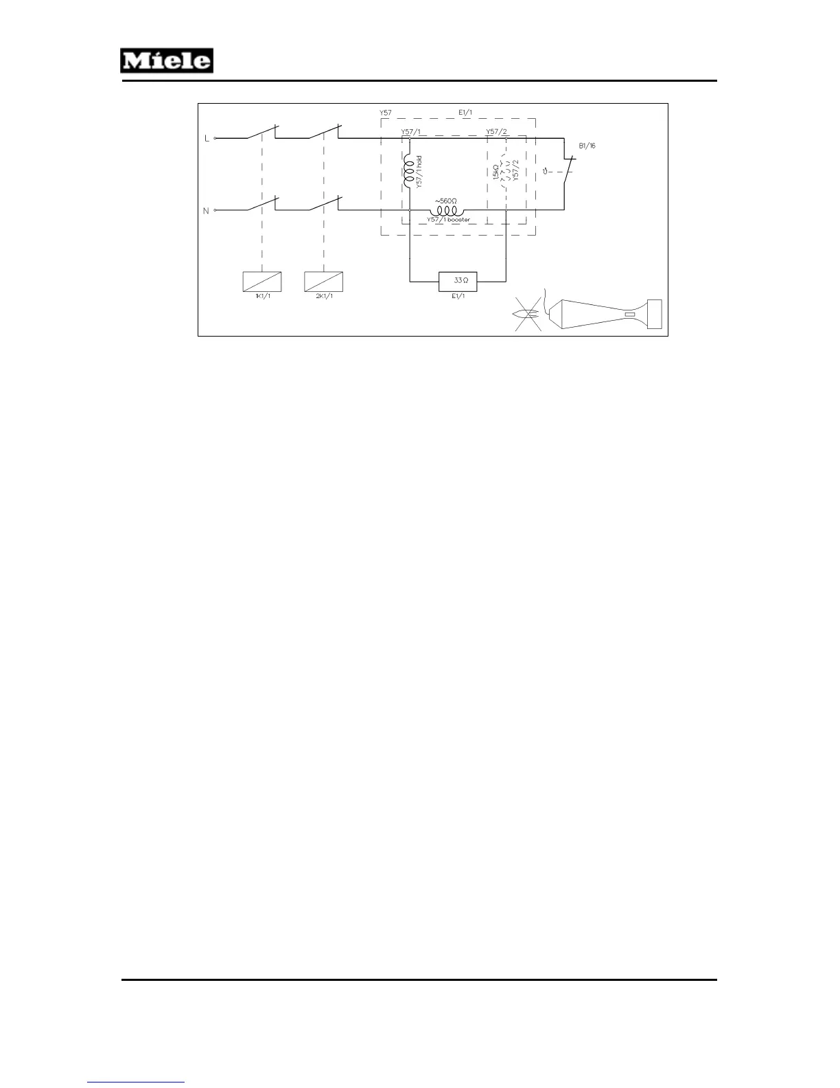
Figure 031-5: Drying Process after Flame Has Gone Out
If the flame goes out, the sluggishness of flame sensor B1/16 will cause gas
to continue flowing until gas solenoid valve Y57/2 closes and stops the gas
flow. For safety time, refer to Section 031-2.1.3. If the burner overheats, the
thermostat/temperature limiter (1F1, 2F1) interrupts the voltage circuit of gas
solenoid Y57, so gas solenoids Y57/1 and Y57/2 shut off.
2.1.3 Safety Time
The safety time is the time span between the point when the flame goes out
and the gas supply shuts off.
2.1.4 Heater Bank NTC (2R30)
Heater bank NTC 2R30 is located at the reflective plate, under the back
service panel. For NTC resistance values, refer to Table 030-3.
2.1.5 Temperature Limiters (1F1, 2F1)
Two ¾” bi-metal temperature limiters (1F1, 2F1) with manual reset at the
burner. The bi-metal temperature limiter 1F1 at the burner exit detects any
overheating of the burner due to insufficient air or air leakage. The bi-metal
temperature limiter 2F1 at the burner entrance detects any flame flashback.