Technical Information
11
T 980x/T 982x
2 T 982x
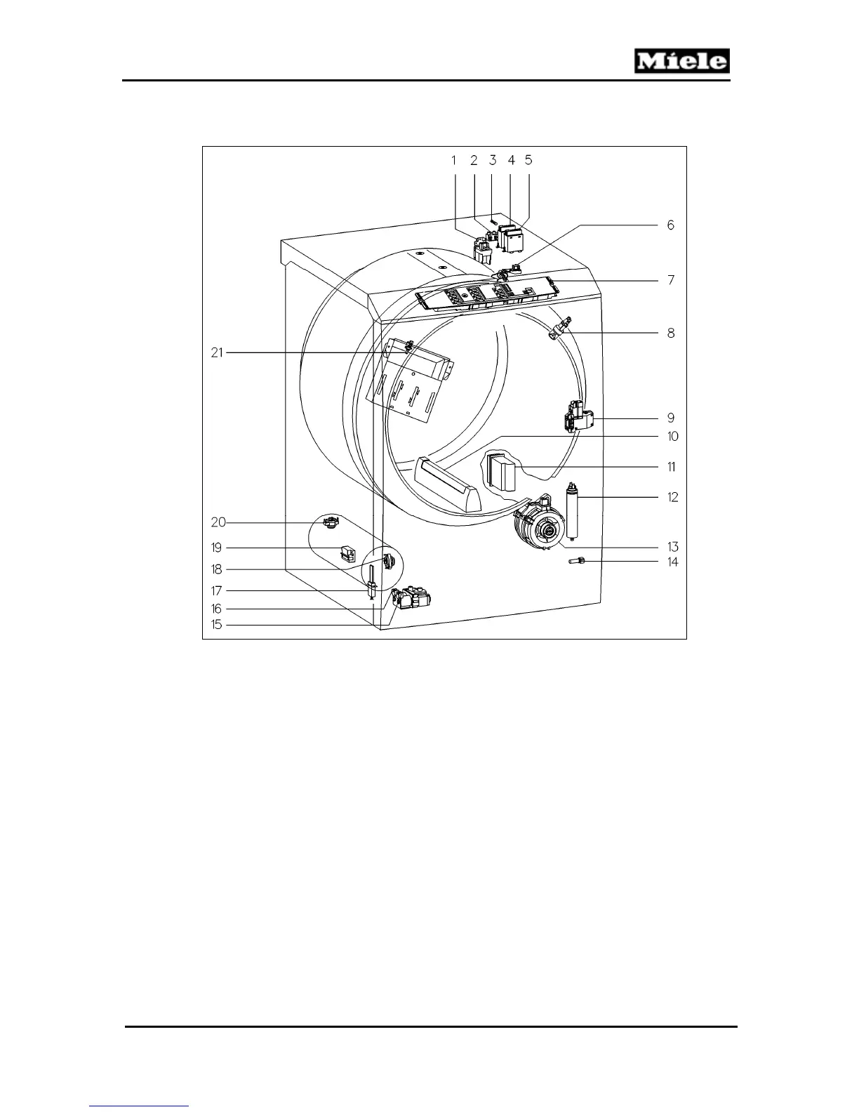
Figure D-2: T 982x Component Layout
1 (Z/1) Interference suppression capacitor 12 (C5) Motor capacitor
2 (X3/1) Terminal block 13 (M5) Motor
3 (F2) Fuse 14 (1R30) Drying air NTC
4 (1K1/1) Heater relay 15 (Y57/1) Gas solenoid
5 (2K1/1) Heater relay 16 (Y57/2) Gas solenoid
6 (B3/1) Residual moisture sensor 17 (E1/1) Igniter electrode
7 (1N1) Electronic (EPWL)
18 (2F1) Temperature limiter flame flashback
w/manual reset
8 (H3/6) Drum light 19 (B1/16)
Flame sensor (radiant output sensor)
9 (A2) Door lock 20 (1F1) Temperature limiter w/manual reset
10 (B3/1) Residual moisture sensor - Drum rib 21 (2R30) Heater bank NTC
11 (WLAN) RemoteVision (optional)