Technical Information
30
T 980x/T 982x
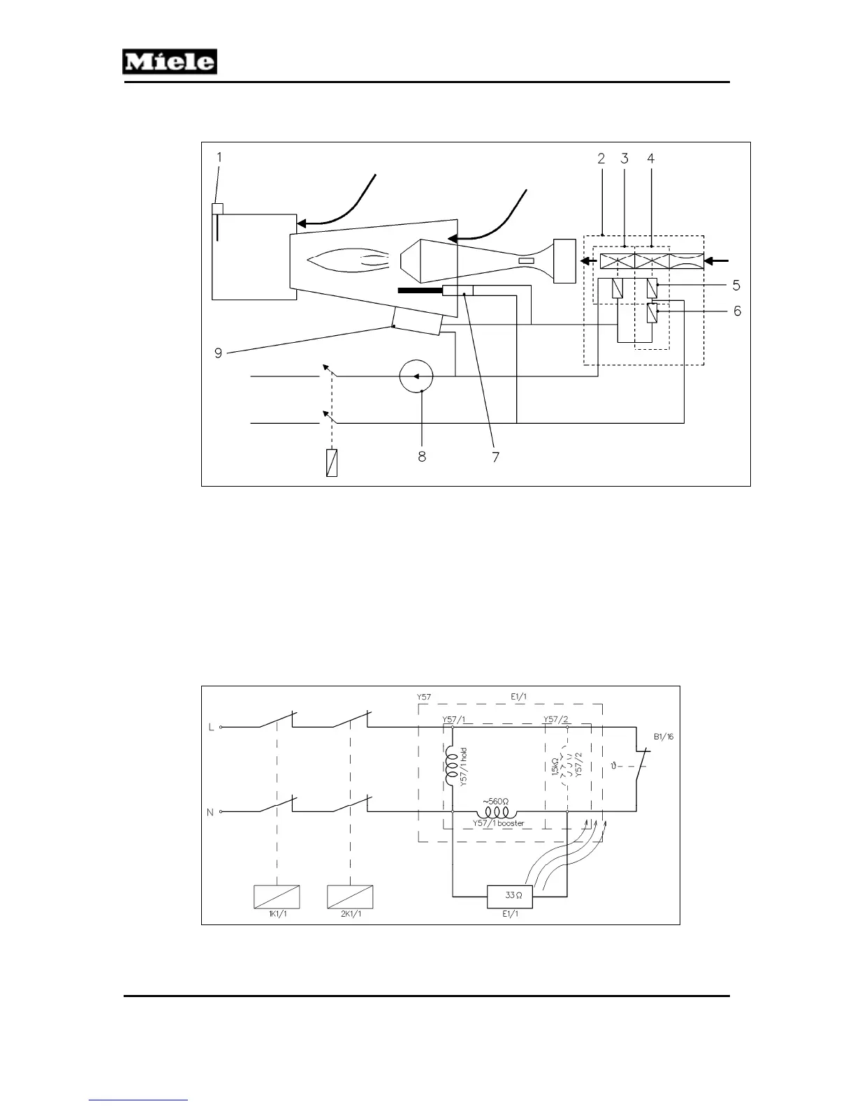
2.1.2 Gas Ignition
Figure 031-1: Gas Ignition Schematic
1 NTC heating (1R30, 2R30) in heating duct
2 Gas solenoid valve Y57
3 Gas solenoid valve Y57/2
4 Gas solenoid valve Y57/1
5 Maintaining coil for gas solenoid valve Y57/1
6 Booster coil for gas solenoid valve Y57/1
7 Igniter E1/1
8 Temperature limiter (1F1, 2F1)
9 Flame sensor (radiance sensor B1/16)
Figure 031-2: Onset of Drying Process, Before Gas Starts to Flow