. A complete Parts List is available at www.MillerWelds.com
OM-261726 Page 21
input4 2012−05 − 803766-C
! Installation must meet all National and
Local Codes − have only qualified per-
sons make this installation.
! Disconnect and lockout/tagout input
power before connecting input con-
ductors from unit. Follow established
procedures regarding the installation
and removal of lockout/tagout
devices.
! Always connect green or green/yellow
conductor to supply grounding termi-
nal first, and never to a line terminal.
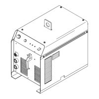
. The Auto-Line circuitry in this unit auto-
matically links the power source to the
primary voltage being applied, either 115
or 230 VAC.
See rating label on unit and check input volt-
age available at site.
1 Input Power Cord
2 Disconnect Device (switch shown in the
OFF position)
3 Disconnect Device Grounding Terminal
4 Disconnect Device Line Terminals
5 Black And White Input Conductor (L1
And L2)
6 Green Or Green/Yellow Grounding
Conductor
Connect green or green/yellow grounding
conductor to disconnect device grounding
terminal first.
Connect input conductors L1 and L2 to dis-
connect device line terminals.
7 Over-Current Protection
Select type and size of over-current protec-
tion using Section 5-8 (fused disconnect
switch shown).
Close and secure door on disconnect device.
Follow established lockout/tagout proced-
ures to put unit in service.
8 Multi-Voltage Plug And Power Cord
Connector (NEMA 6-50P Plug Shown)
For multi−voltage plug connections, see Sec-
tion 5-12.
9 Receptacle (NEMA 6-50R)
(Customer Supplied)
Connect plug to receptacle.
5-11. Connecting 1-Phase Input Power (Continued)
Notes