ENGLISH
OM-363 Page 13
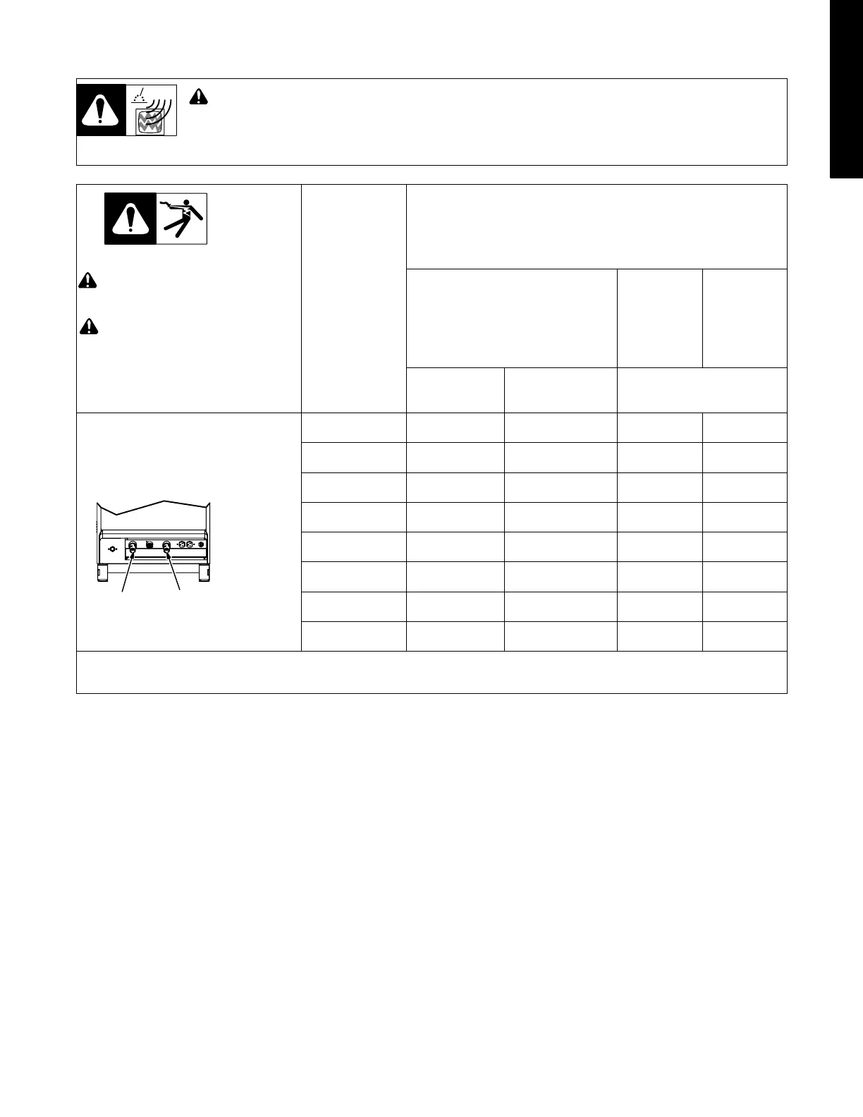
3-8. Weld Output Terminals And Selecting Cable Sizes
To reduce possible interference, keep weld cables as short as possible, close together, and down low, such as on the floor.
Locate welding operation 100 meters from any sensitive electronic equipment. Be sure this welding machine is installed
and grounded according to this manual. If interference still occurs, the user must take extra measures such as moving
the welding machine, using shielded cables, using line filters, or shielding the work area.
! ARC WELDING can cause Electromagnetic Interference.
! Do not use worn, dam-
aged, undersized, or
poorly spliced cables.
Weld Output
Terminals
! Turn off power before
connecting to weld
output terminals.
Total Cable (Copper) Length In Weld Circuit Not Exceeding
100 ft (30 m) Or Less
150 ft
(45 m)
200 ft
(60 m)
Welding Am-
peres
10 − 60% Duty
Cycle
60 − 100% Duty
Cycle
10 − 100% Duty Cycle
Electrode
Work
Ref. 803 588-B
100 4 4 4 3
150 3 3 2 1
200 3 2 1 1/0
250 2 1 1/0 2/0
300 1 1/0 2/0 3/0
350 1/0 2/0 3/0 4/0
400 1/0 2/0 3/0 4/0
500 2/0 3/0 4/0 2-2/0
Weld cable size (AWG) is based on either a 4 volts or less drop or a current density of at least 300 circular mils per ampere
*Select weld cable size for pulsing application at peak amperage value.. S-0007-D

 Loading...