OM-363 Page 42
4-12. Pulse Controls (Standard On 350 LX Models, Optional On 250 DX Models)
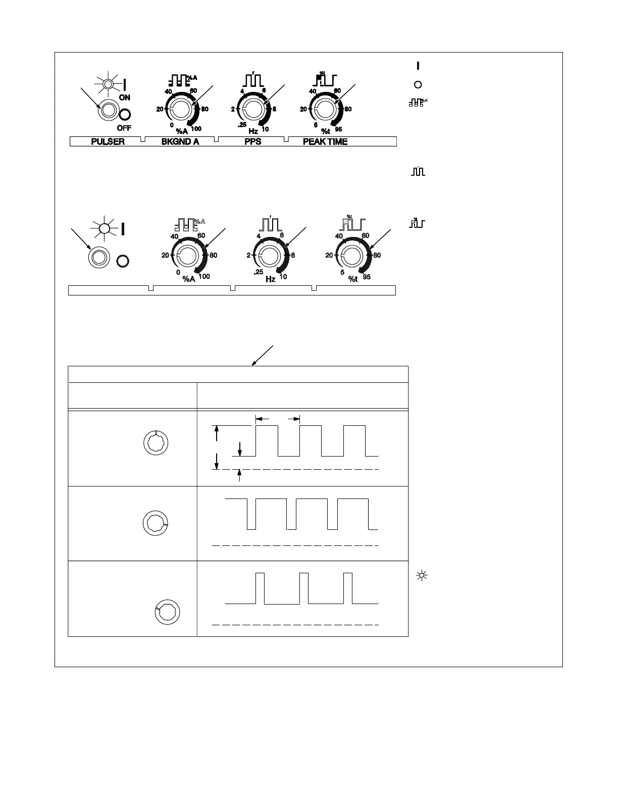
1 On/Off Control
Use control to turn pulse function
On and Off.
2 Background Amps
Use Background Amps control to
set the low pulse of the weld amper-
age, which cools the weld puddle
and affects overall heat input.
Background Amps is set as a per-
centage of peak amperage.
3 Pulse Frequency
Ranges from 0.25−10.0 pps
(pulses per second). Control is
used to determine appearance of
weld bead.
4 Peak Time
A range of 5−95% of each pulse
cycle can be spent at the peak am-
perage level.
Peak amperage (3-310 amps for
250 DX models, and 3−400 amps
for 350 LX models), is set with the
Amperage Adjustment control (see
Section 4-1). Peak amperage is the
highest welding amperage allowed
to occur in the pulse cycle. Weld
penetration varies directly with
peak amperage.
5 Pulsed Output Waveforms
Example shows affect changing
the Peak Time control has on the
pulsed output waveform.
Application:
Pulsing refers to the alternating
raising and lowering of the weld
output at a specific rate. The raised
portions of the weld output are con-
trolled in width, height, and frequen-
cy, forming pulses of weld output.
These pulses and the lower amper-
age level between them (called the
background amperage) alternately
heat and cool the molten weld
puddle. The combined effect gives
the operator better control of pene-
tration, bead width, crowning, un-
dercutting, and heat input. Controls
can be adjusted while welding.
Pulsing can also be used for filler
material addition technique
training.
NOTE: Function is enabled, when
LED is lit.
Peak Amp
Bkg Amp
Balanced
More Time
At Peak
Amperage
More Time At
Background
Amperage
Pulsed Output Waveforms
Percent (%) Peak
Time Control Setting
(50%)
(80%)
(20%)
PPS
5
1
2
3
4
(CE Nameplate)
1
2
3
4