OM-363 Page 50
SECTION 6 − TROUBLESHOOTING
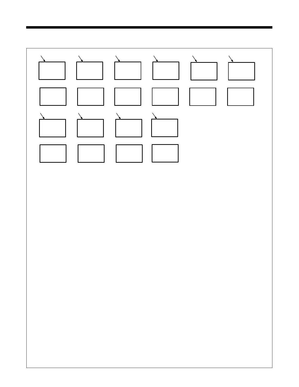
6-1. Voltmeter/Ammeter Help Displays
A
V
A
V
3
A
V
HLP
--1
HLP
--2
HLP
--3
A
V
HLP
--4
A
V
HLP
--5
2 51 4
A
V
HLP
--9
6
A
V
HLP
-10
7
A
V
HLP
-11
8
A
V
HLP
--0
0
A
V
HLP
-12
9
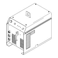
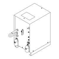
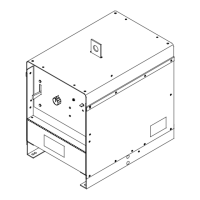
All directions are in reference to the front of the unit. All cir-
cuitry referred to is located inside the unit.
0 Help 0 Display
Indicates a short in the thermal protection circuitry located on the
transformer/stabilizer of the unit.
1 Help1 Display
An SCR overcurrent or undercurrent condition has occurred.
Turn power off and back on to correct condition.
2 Help 2 Display
Indicates an open in the thermal protection circuitry located on
the transformer/stabilizer of the unit.
3 Help 3 Display
Indicates the transformer/stabilizer of the unit has overheated.
The unit has shut down to allow the fan to cool it (see Section
3-6). Operation will continue when the unit has cooled.
4 Help 4 Display
Indicates an open in the thermal protection circuitry located on
the rectifier assembly of the unit.
5 Help 5 Display
Rectifier assembly has overheated. The unit has shut down to
allow the fan to cool unit (see Section 3-6). Operation will contin-
ue when the unit has cooled.
6 Help 9 Display
Indicates a short in the thermal protection circuitry located on the
rectifier assembly of the unit.
7 Help 10 Display
Indicates Remote Output control is activated. Release Remote
Output control to clear help message.
8 Help 11 Display
Output Selector switch is not in correct position (see Section
4-2).
9 Help 12 Display
Indicates a non-allowable set-up of the front panel.