OM-363 Page 22
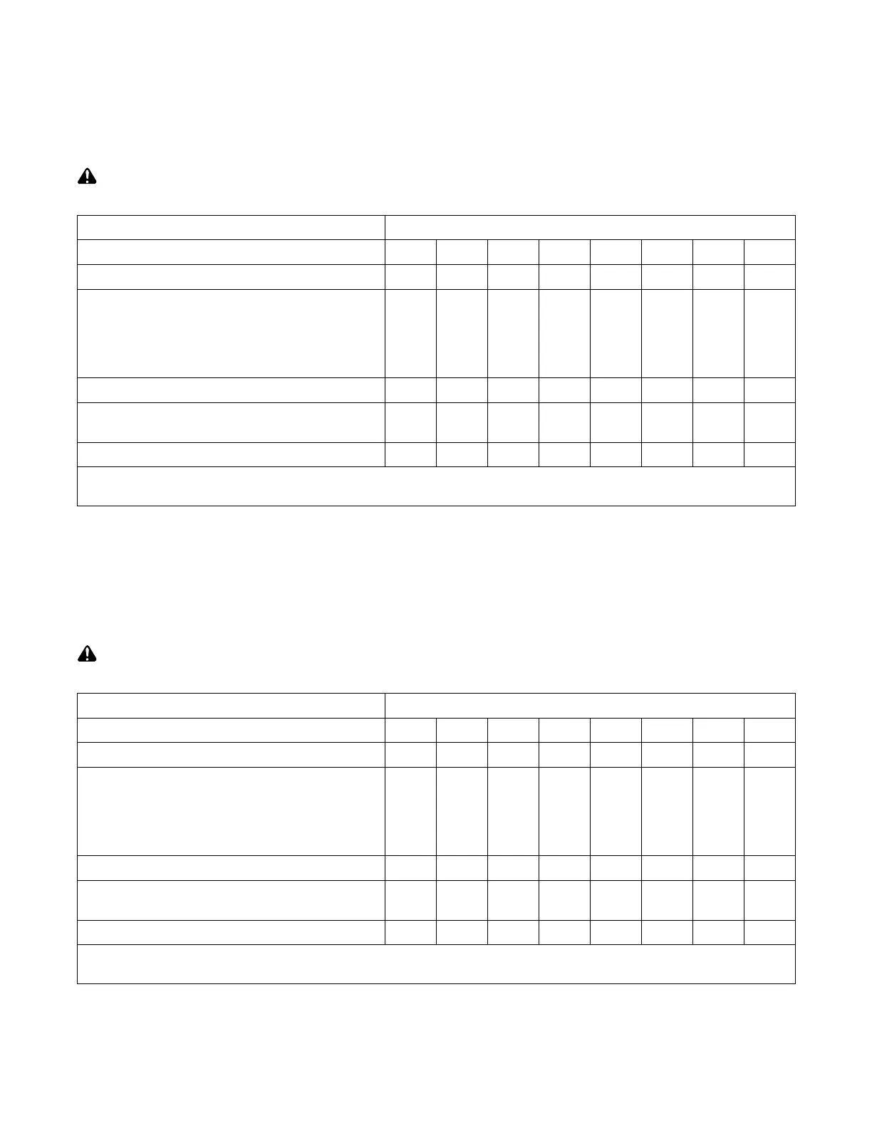
3-19. Electrical Service Guide
A. For 250 DX Models
All values in both tables were calculated at 60% duty cycle.
Actual input voltage cannot exceed ± 10% of indicated required input voltage shown in both tables. If actual input voltage is outside of this range,
damage to unit may occur.
Failure to follow these electrical service guide recommendations could create an electric shock or fire hazard. These recommenda-
tions are for a dedicated branch circuit sized for the rated output and duty cycle of the welding power source.
50/60 Hertz Models Without Power Factor Correction
Input Voltage
200 220 230 400 440 460 520 575
Input Amperes At Rated Output*
88 82 77 45 41 38 35 31
Max Recommended Standard Fuse Or Circuit Breaker
Rating In Amperes Circuit Breaker
1
Time-Delay Fuse
2
125 125 125 70 60 60 50 45
Normal Operating (Fast) Fuse
3
125 125 125 70 60 60 50 45
Min Input Conductor Size In AWG
4
4 6 6 8 8 10 10 10
Max Recommended Input Conductor Length In
Feet (Meters)
167
(51)
137
(42)
153
(47)
305
(93)
369
(112)
281
(86)
352
(107)
439
(134)
Min Grounding Conductor Size In AWG
4
6 6 6 8 10 10 10 10
* Input amperes at rated output is the amperage draw for that particular input voltage if the machine is run at its rated welding
output (see Section 3-5 for rated welding output).
Reference: 2005 National Electrical Code (NEC)
1 If a circuit breaker is used in place of a fuse, choose a circuit breaker with time-current curves comparable to the recommended fuse.
2 “Time-Delay” fuses are UL class “RK5” .
3 “Normal Operating” (fast) fuses are UL class “K5” (up to and including 60 amp), and UL class “H” ( 65 amp and above).
4 Conductor data in this section specifies conductor size (excluding flexible cord or cable) between the panelboard and the equipment per NEC Table
310.16. If a flexible cord or cable is used, minimum conductor size may increase. See NEC Table 400.5(A) for flexible cord and cable requirements.
Failure to follow these electrical service guide recommendations could create an electric shock or fire hazard. These recommenda-
tions are for a dedicated branch circuit sized for the rated output and duty cycle of the welding power source.
50/60 Hertz Models With Power Factor Correction
Input Voltage
200 220 230 400 440 460 520 575
Input Amperes At Rated Output*
60 61 52 34 31 26 26 21
Max Recommended Standard Fuse Or Circuit Breaker
Rating In Amperes Circuit Breaker
1
Time-Delay Fuse
2
90 90 80 50 45 40 40 30
Normal Operating (Fast) Fuse
3
90 90 80 50 45 40 40 30
Min Input Conductor Size In AWG
4
8 8 8 10 10 10 10 12
Max Recommended Input Conductor Length In
Feet (Meters)
87 (26)
102
(31)
115
(35)
226
(69)
274
(84)
308
(94)
383
(117)
295
(90)
Min Grounding Conductor Size In AWG
4
8 8 8 10 10 10 10 12
* Input amperes at rated output is the amperage draw for that particular input voltage if the machine is run at its rated welding
output (see Section 3-5 for rated welding output).
Reference: 2005 National Electrical Code (NEC)
1 If a circuit breaker is used in place of a fuse, choose a circuit breaker with time-current curves comparable to the recommended fuse.
2 “Time-Delay” fuses are UL class “RK5” .
3 “Normal Operating” (fast) fuses are UL class “K5” (up to and including 60 amp), and UL class “H” ( 65 amp and above).
4 Conductor data in this section specifies conductor size (excluding flexible cord or cable) between the panelboard and the equipment per NEC Table
310.16. If a flexible cord or cable is used, minimum conductor size may increase. See NEC Table 400.5(A) for flexible cord and cable requirements.