OM-363 Page 14
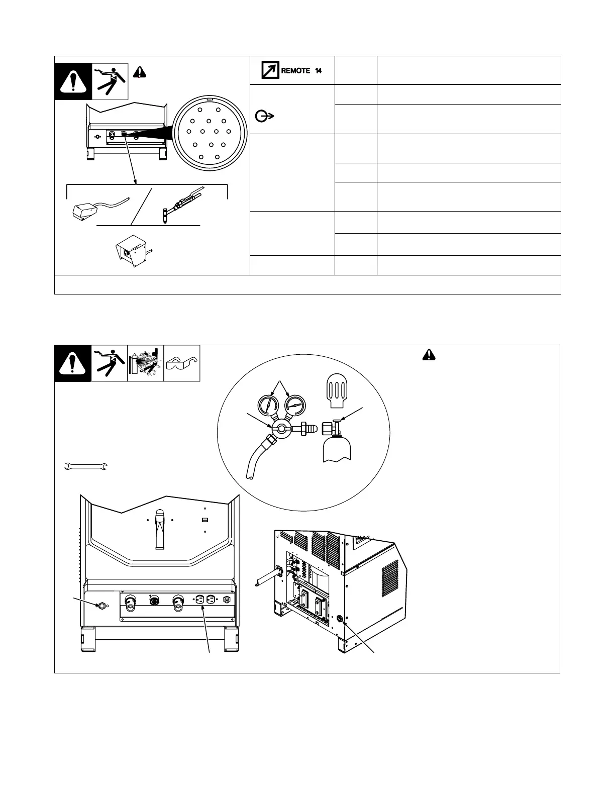
3-9. Remote 14 Receptacle Information
Ref. 803 588-B
AJ
B
K
I
C
L
NH
D
M
G
E
F
! Turn off power before
connecting to receptacle.
Socket* Socket Information
24 VOLTS DC
OUTPUT
CONTACTOR
A Contactor control 24 volts dc.
B Contact closure to A completes 24 volts dc
contactor control circuit and enables output.
REMOTE
OUTPUT
CONTROL
A
C Output to remote control; 0 to +10 volts dc output
to remote control.
D Remote control/feedback circuit common.
E 0 to +10 volts dc input command signal from
remote control.
A/V
AMPERAGE
VOLTAGE
F Current feedback; +1 volt dc per 100 amperes.
H Voltage feedback; +1 volt dc per 10 volts output.
GND
K Chassis common.
*The remaining sockets are not used.
3-10. Shielding Gas Connections And 115 Volts AC Duplex Receptacle
Ref. 803 588-B / Ref. 803 585-B / Ref. 157 858
! Turn Off power before con-
necting to receptacle.
1 Gas Valve In Connection
Located on rear of unit.
2 Gas Valve Out Connection
Connections have 5/8-18 right-
hand threads.
3 Cylinder Valve
Open valve slightly so gas flow
blows dirt from valve. Close valve.
4 Regulator/Flow Gauge
Connect regulator/flow gauge to
gas cylinder.
Connect customer supplied gas
hose between regulator/flow gauge
and gas in fitting.
5 Flow Adjust
Typical flow rate is 20 cfh (cubic feet
per hour).
6 115 V 15 Amp AC Receptacle
Receptacle is protected from over-
load by circuit breaker CB1 (see
Section 5-3).
5
6
4
2
5/8, 3/4, 1-1/8 in
Tools Needed:
3
Front View
1
Rear View

 Loading...