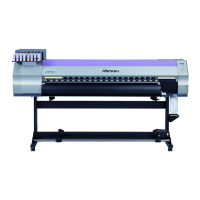
Color Inkjet Printer JV33-130/160
5-10
5-2-9. Head memory PCB
Board name: Head memory PCB assembly (E104428)
Head ID information is stored. Assembled to be integrated into the head.
Head memory PCB connector signals
5-2-10. LED PCB
Board name: LED PCB assembly (E104988)
Located inside the left cover on the top and front of the ink cartridge unit.
The FFC from the X-axis relay PCB is connected to it. It performs display control of the LEDs (green,
red) corresponding to each slot of the cartridge.
<Head memory PCB connector signals>
CN No Pin Connected to: Silk display Notice
CN1 3 Head warm thermistor
CN2 11 Head relay PCB
CN3 2 Head warm heater
CN4 2 Head warm heater

 Loading...


