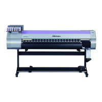
Color Inkjet Printer JV33-130/160
vi
3-3-3. Capping Assembly .......................................................................... 3-13
3-3-4. Major Parts for Washing Cartridge Assembly ................................ 3-15
3-4. Overhaul of PCBs ....................................................................................... 3-18
3-4-1. Main PCB ....................................................................................... 3-19
3-4-2. Station PCB .................................................................................... 3-25
3-5. Overhaul of Sensors ................................................................................... 3-26
3-6. Overhaul of Driving Parts ......................................................................... 3-27
3-6-1. X-axis Motor ................................................................................... 3-28
3-6-2. Y-axis Motor ................................................................................... 3-31
3-6-3. Y-axis Drive Pulley ......................................................................... 3-35
3-6-4. Y Drive Belt .................................................................................... 3-39
3-6-5. Wiper Unit ...................................................................................... 3-42
3-7. Overhaul of Other Parts ............................................................................ 3-44
3-7-1. Cutter Unit Assembly ..................................................................... 3-45
3-7-2. Linear scale ..................................................................................... 3-48
3-7-3. Adjustment of the station height ..................................................... 3-50
Troubleshooting
4-1. Outline ........................................................................................................... 4-2
4-1-1. Rough identification of the source of the trouble ............................. 4-2
4-1-2. Checking procedure .......................................................................... 4-2
4-2. Troubles for which error messages are displayed ..................................... 4-4
4-2-1. Error messages and corrective measures .......................................... 4-4
4-2-2. Warning messages and corrective measures ................................... 4-10
4-3. Detailed Methods of Coping with the Malfunctions ............................... 4-13
4-3-1. Electrical Troubleshooting .............................................................. 4-13
Explanation of Electrical Parts
5-1. Outline ........................................................................................................... 5-2
5-1-1. Operation Explanation ...................................................................... 5-3
5-1-2. Power Supply .................................................................................... 5-4
5-2. Circuit Board Specifications ....................................................................... 5-6
5-2-1. Main PCB ......................................................................................... 5-6
5-2-2. PRAM PCB ...................................................................................... 5-7
5-2-3. Station PCB ...................................................................................... 5-7
5-2-4. X-axis motor relay PCB ................................................................... 5-8
5-2-5. Ink slider PCB .................................................................................. 5-9
5-2-6. Keyboard PCB .................................................................................. 5-9
5-2-7. Encoder PCB .................................................................................... 5-9
5-2-8. Take-up PCB ..................................................................................... 5-9
5-2-9. Head memory PCB ......................................................................... 5-10
5-2-10. LED PCB ........................................................................................ 5-10
5-3. Electronic block diagram ........................................................................... 5-11
5-3-1. Connection diagram inside main unit ............................................. 5-11
5-3-2. Connection diagram outside main unit ........................................... 5-13
 Loading...


