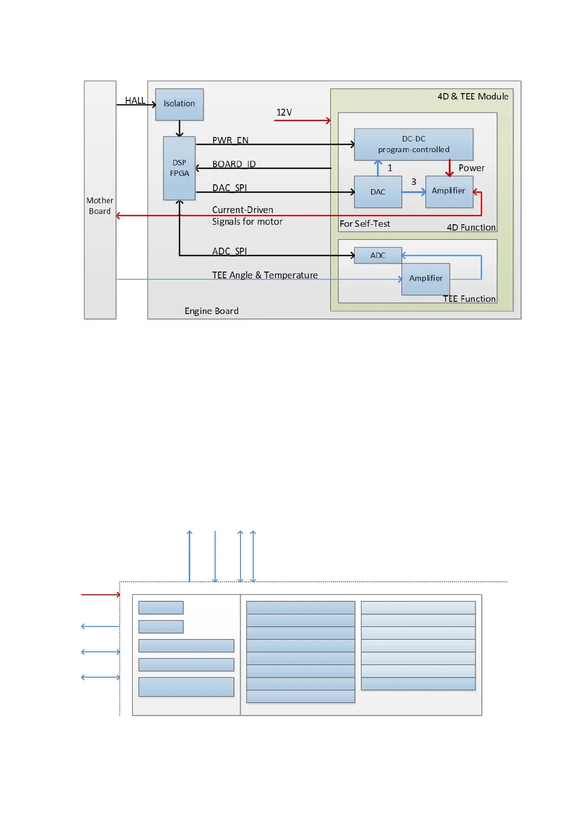
4-8 Product Principle
Figure 4-6 Schematic diagram of 4D&TEE module
4.2.6 ECG Module
ECG test and PCG test can be achieved on ECG module.
ECG module communicates with engine board via UART.
4.3 Ultrasound Back-end Unit
Taking PC module as the center, back-end unit is the platform of the ultrasound software system. It
takes charge of back-end’s central control. It also offers the calculation capacity for image
post-processing, user information storage, the display and the interaction, etc.
Back End
Power
AC output
Control
PHV Control
Monitoring
PCI-E Bus
Reset
Configuration
Status
JTAG
Touch Screen Device
Hard Disk/DVD-RW
Speaker
Control Panel
Primary Display Device
Secondary Display Device Wireless Network
Digital Video Output
Audio Output
Printer
Analog Video Output
USB Ports
Wired Network
Fans
PC Module
MF FPGA
Back-End Monitoring
IO Expansion
PC Unit
PC Manager (EC)
Microphone
IO Interfaces and Devices
Figure 4-7 Diagram of back-end unit