63
7−7. Change of bridge power supply voltage
Warning ● Prior to change the bridge power supply voltage, set the power OFF
for the instrument. If neglected, there may cause unexpected failure.
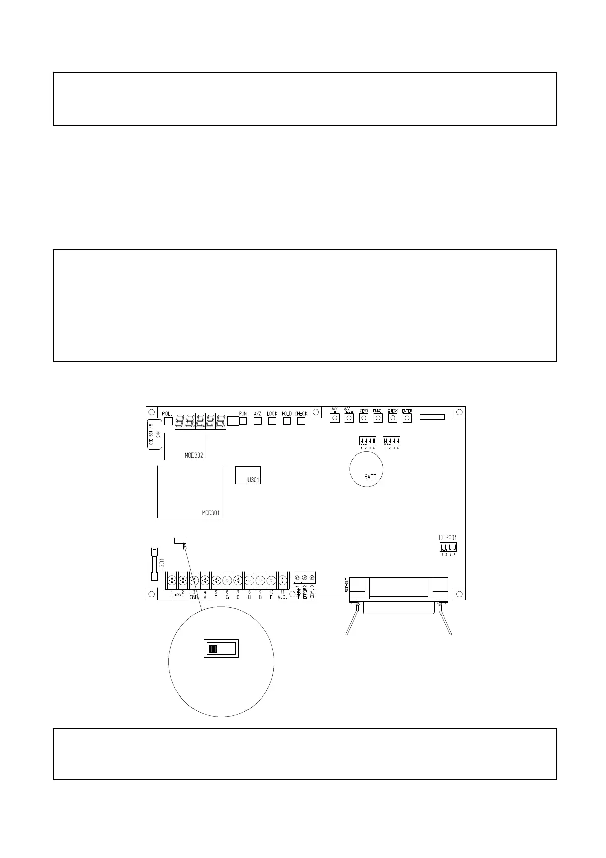
The instrument can select bridge power supply from “10 V“ and “2.5 V”.
This selection can be made with the SW1 “Changeover SW for bridge power supply” located on the
board. (Refer to the below figure.) When the SW1 is changed to the left side, it will become 10 V
and to the right side, it will become 2.5 V. As for default, “10 V” has set.
When the instrument is applied in the system when zener barrier is used, be sure to select 2.5 V for
bridge power supply beforehand.
Warning ● When using the instrument in the system with zener barrier applied,
be sure to use it at 2.5 V of bridge power supply voltage.
If neglected, there may cause failure in the instrument. However, the
case when the instrument and strain gage applied transducer(s) are
connected with 4 cores shielded cable, is excluded.
Above explanation is the case when CAB−501(6 wires) for the cable and 350 Ω type for the load
cell are applied.
10 V
SW1
2.5 V
Enlarged Fig.
Bridge Voltage
Left:10 V
Right:2.5 V
● When bridge power supply voltage has changed, apply calibration
again.
CN202
DIP202
DIP203