55
● P.C. output transistor will be OFF (Positive logic electrically) at the
time of HOLD signal input. However, as for P.C., it will be OFF
condition after one shot of operation is over.
● After inputting HOLD signal, the following response times will be
required until DATA and POL. are frozen or HOLD is cancelled.
At 50 times/s:Approx.120 ms at max.
At 20 times/s:Approx. 150 ms at max.
At 4 times/s:Approx. 350 ms at max.
7−2−6. Output condition
Transisto
Pin−COM level
ett
ng output
og
c
utput
ata
condition
w
en vo
tage
s
supplied externally.
Ye s ON L
egat
ve
og
c
No OFF H
Ye s OFF H
os
t
ve
og
c
No ON L
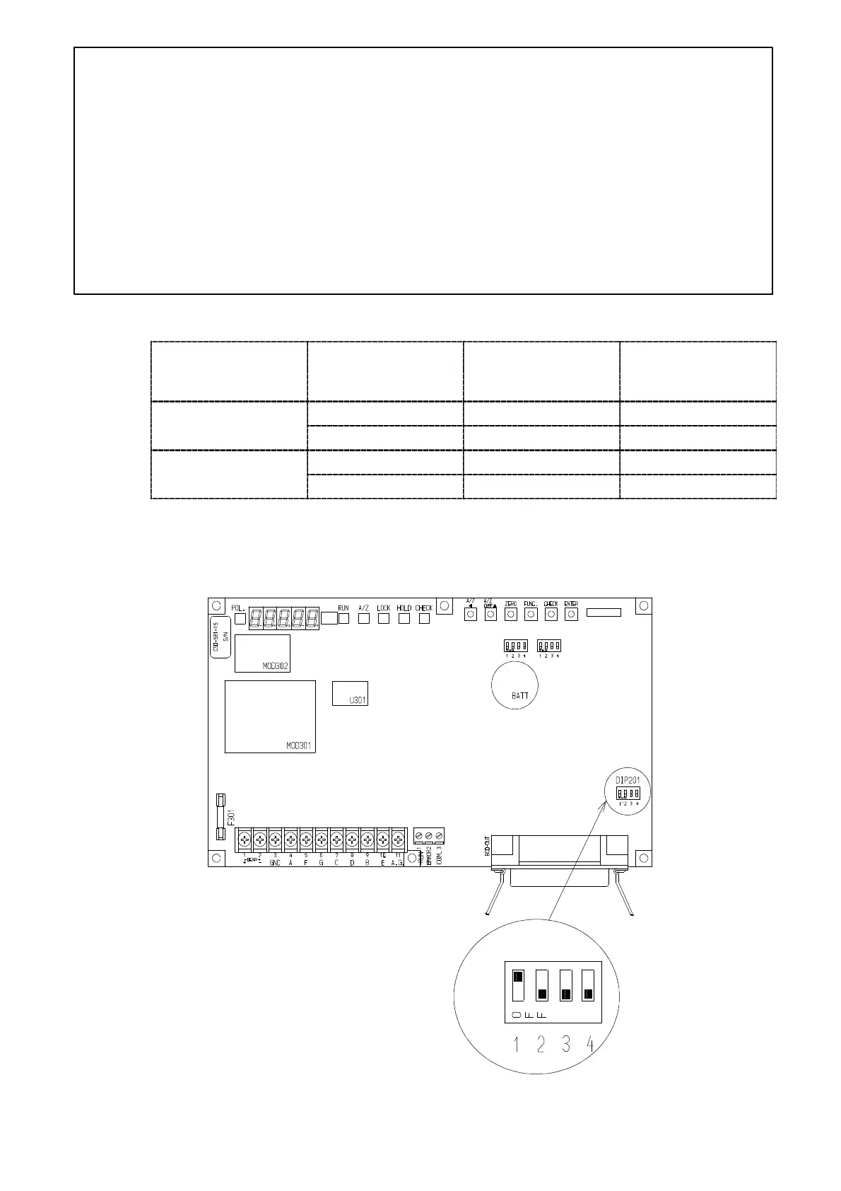
7−2−7. Selection of output logic for P.C.(Print command), and its width
The selection of P.C. logic, width for the instrument can be performed with the DIP201 “DIP SW
for the setting of P.C. output” on the P.C. board. (Refer to the below figure.)
UP↑
Down↓
ON
OFF
Enlarged Fig.
CN202
DIP202
DIP203